Tag Archives: building envelope science

Post-Modern Higher Education Facility Assessment

BACKGROUND
Construction means and methods of masonry veneer walls, and particularly flashing systems needed for protection from water intrusion of those veneer walls, was well known in the Post-Modern era (circa 1980’s – 1990’s). Many professional organizations and industries (e.g. Brick Institute of America) published technical documents as guides to proper construction of masonry veneer walls.

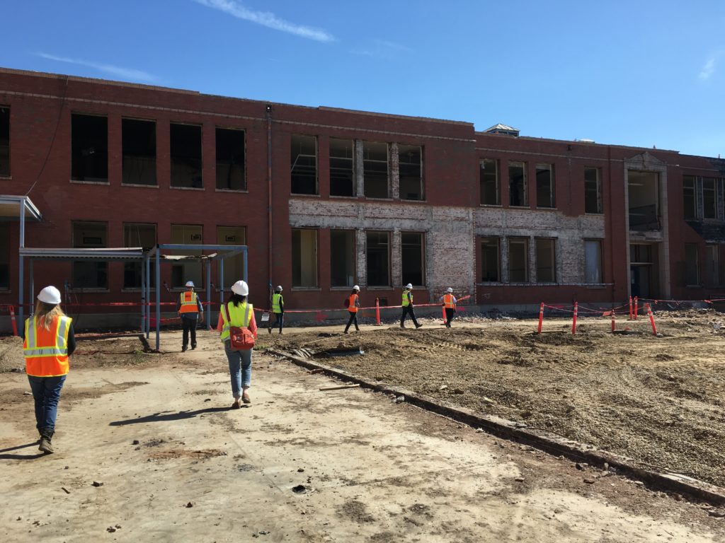
PMA was retained to conduct a building envelope enclosure assessment of a Post Modern masonry veneer building, over the Owner’s concern of advanced deteriorated conditions of precast window sills. The purpose of the assessment was to provide the Owner an understanding of the extent of the precast failures, whether or not any other materials were impacted by the failed conditions, and to provide an analysis of potential cause and a rough order of magnitude cost of potential mitigation. The Owner also sought an evaluation of the effectiveness of a proposal to install sheet metal over the sills to prolong the life of the precast for another forty years.
PoMo-EME-Building-Assessment-WSU
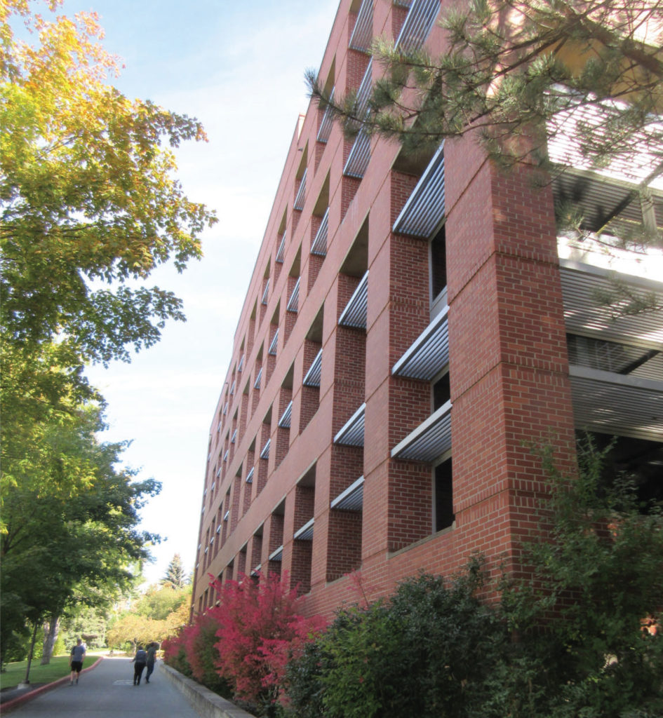
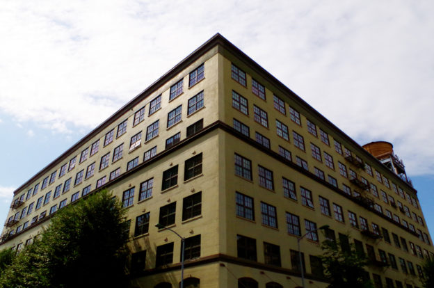
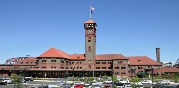
The circa 1984 Post Modern masonry veneer building links two existing historic academic classroom buildings and functions as both laboratory space and faculty offices. The building is an off-set “T” in plan with the leg of the T forming the link between the existing academic structures. A six-story faculty office tower, rises between the existing structures on the east end of the leg. The majority of the window openings occur along the bar of the T on the west elevation. The building wall cross section, from exterior to interior, is comprised of a single course of masonry veneer, a 1.5 inch air gap, an 12 inch thick cast in place concrete structural frame, a 4 inch air gap, steel stud framing, and one layer of interior gypsum board. Given the laboratory program, there is a strong interior positive air pressure that creates significant air flow within the interior air gap between the gypsum board and concrete frame. There have been no major renovations of the building since its construction.

ASSESSMENT PROCESS
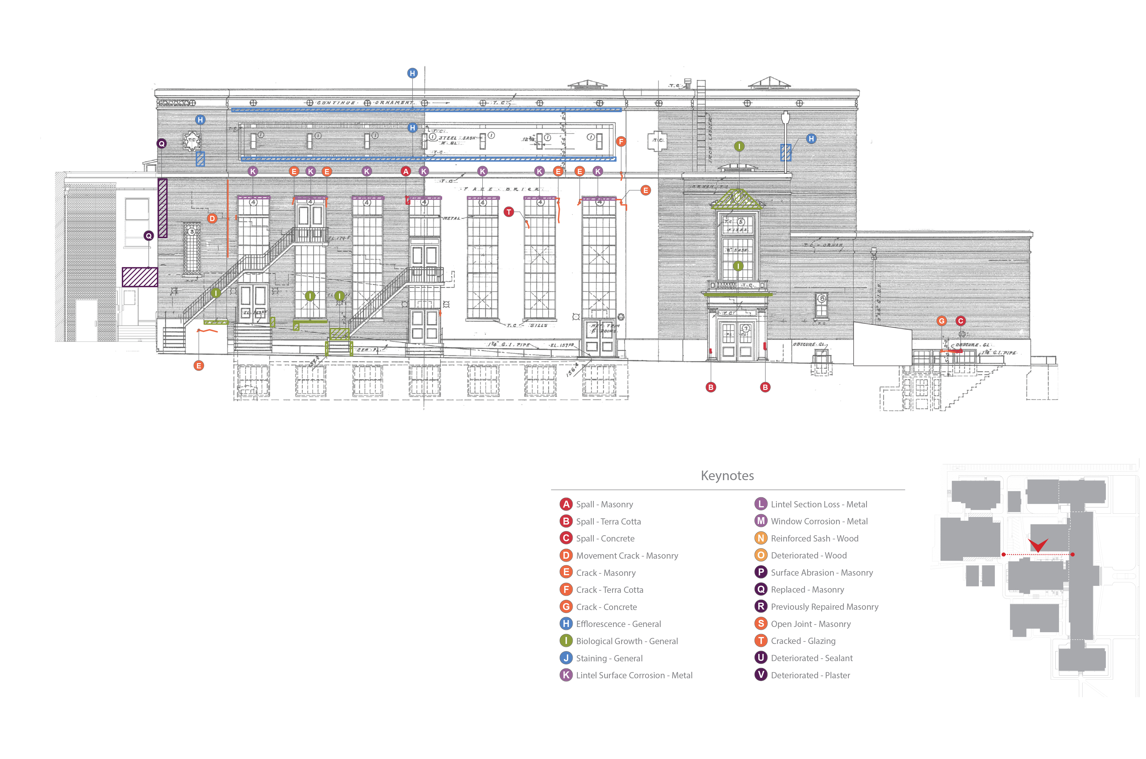
PMA conducted a two-part assessment program. Part 1 consisted of a visual only assessment performed on the precast window sills, precast window headers, masonry veneer mortar joints, sealant joints, and interior gypsum board adjacent to the aluminum window sill corners. Review of the 1984 original design documents and detail book were used to augment the on-site observations.

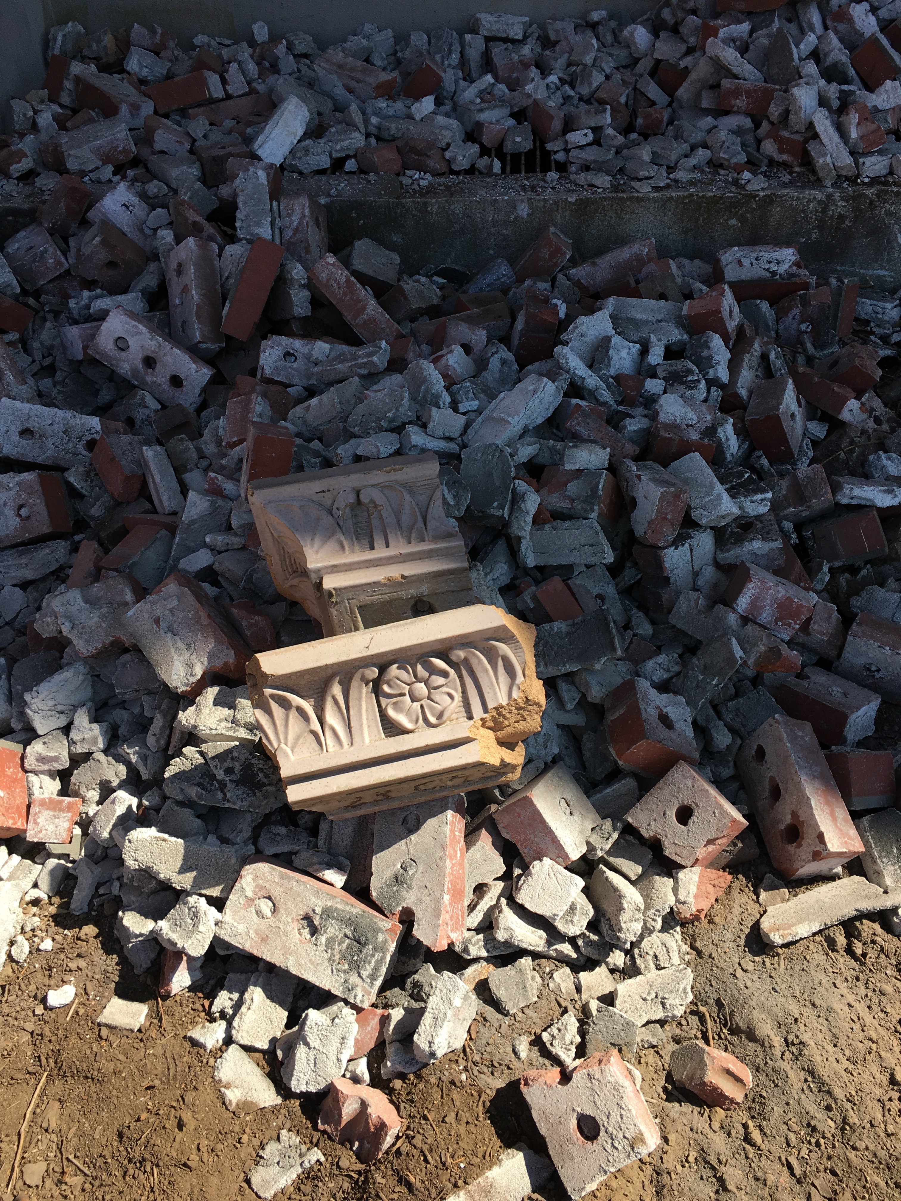
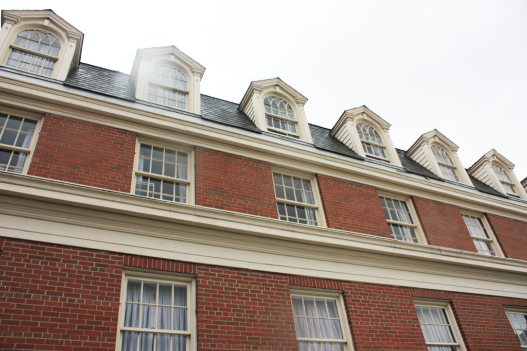
Visual observations of the exterior face of the veneer identified the extent of the aforementioned pre-cast sill damage, previous repairs and subsequent further cracking to the pre-cast window headers, mortar popping out of the joints, sealant failure along masonry control joints, rust staining corresponding to the veneer ledgers, and weeps were not visible along the ledger locations. In addition, dirt, debris, and other exterior material had blocked the built-in aluminum window frame weep holes.

In review of the design documents, it was noted that not all details followed industry standards. In specific, flashing was absent from some details. Other details indicated an incomplete flashing system for adequate protection of veneer walls. No three dimensional drawings for indicating flashing termination were included.

Part 2 of the assessment involved creating openings in the wall system both on the exterior and the interior. The purpose of the invasive openings was to verify that the wall was constructed as designed, to confirm if additional flashing was installed, and to determine if water intrusion was contributing to the visible damage. Given the degree of deterioration observed on the exterior, target locations for wall openings were performed of the interior face of the gypsum board immediately adjacent to the interior aluminum window sills.
PoMo-EME-Building-Assessment-WSU
FINDINGS
The results of the invasive openings were significant in providing evidence of how lack of proper flashing can damage wall components while high internal positive air pressure can limit the damage to interior systems and protect veneer building envelope enclosure systems from extensive water intrusion.

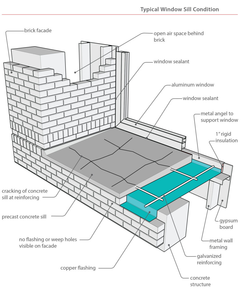
The as‐built conditions, in some locations, varied considerably from the design details. No flashing was installed below the pre-cast window sills and no flashing was installed along the interface between the vertical window system and veneer walls. An outer layer of backer rod behind the vertical sealant joint and inner layer of backer rod behind the gypsum board were the only line of defense against water intrusion. Adequate and substantial copper flashing protected the steel ledger but all rope weeps (a common Post-Modern era construction material for veneer walls) were installed at proper spacing but did not extend to the exterior thereby trapping water against the ledger angles. Beyond the initial outer layer of defense against water intrusion (sealant system, veneer wall, and aluminum window system) there is no back up / secondary protection in place.

No interior finish systems appear to be damaged. The lack of adequate flashing does not currently create interior water intrusion. Current water intrusion is isolated to materials outward of the concrete structural frame. The lack of damage to the interior can be attributed to the high positive air pressure which in turn creates high volume of air flow within the interior air gap inward of the concrete frame. This positive pressure acts as a mitigating element against bulk water intrusion. Combined with the thickness of the concrete structural wall (approximately 12 inches), water intrusion is isolated to the masonry veneer system. Even at the aluminum window frame interface, the two layer of backer rod are sufficient to block water intrusion with a positive air pressure environment.
PoMo-EME-Building-Assessment-WSU
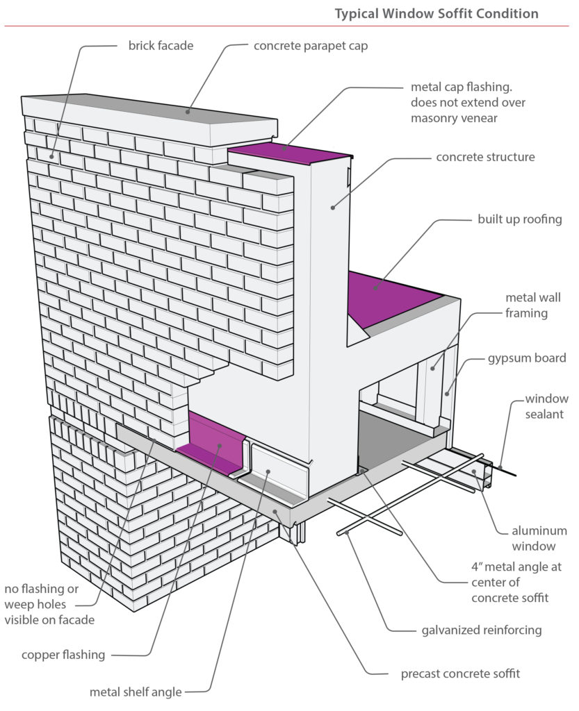
Recently installed new roof coping provided the means to mitigate the lack of through wall flashing along the parapet and greatly reduced water intrusion in the veneer wall air cavity. Given the age of the building, and visual observations, damage has already occurred prior to the new roof coping. In addition, the lack of flashing increases the need to routinely replace deteriorated sealant systems and maintain weeps on both the veneer wall and the aluminum window system. The extensive existing damage to the pre-cast components will require full replacement. During replacement, further assessment of structural components can be made and adequate flashing and weeps can be installed. The pre-cast replacement process may also serve as an opportunity to mock up potential secondary defense systems at the aluminum window frame/veneer wall interfaces. At this time the laboratory use requiring positive air pressure is protecting the interior. However, should the use of the building coincide with lowering of the pressure and air flow, a secondary means to prevent water intrusion will be required. For now, the large amount of air flow with in the cavity provides sufficient temperature and flow volume to adequately dry the cavity space.

Veneer systems, especially those constructed during the Post-Modern era require attention to the flashing details and corollary protective systems like sealant joints, weep holes, and preventive maintenance procedures to prolong the life of the structure and reduce the need for substantial repairs.


Written by Peter Meijer, AIA, NCARB / Principal, and PMA architectural staff.

Presenting on Field Observations of Masonry Failures

Last month the Portland Chapter of RCI- a local chapter of the international association of professionals that specialize in the “specification and design of roofing, waterproofing and building envelope systems” (RCI PDX) hosted a two-day Education Symposium focused on Exterior Walls Quality Assurance & Building Envelope Presentations. The first day of the symposium was geared towards industry professionals “interested in performing observation to assure that exterior wall systems are installed in accordance with construction documents. The program covered diverse topics in the construction of exterior walls, and was intended for manufacturers, general contractors, quality assurance observers, and field inspectors.” (RCI PDX) While the second day was dedicated to Building Envelope Presentations. In addition to attending the first day of the symposium, Peter R. Meijer, AIA, NCARB, and Hali Knight presented on: When the Field Report of Masonry Does Not Correlate with Lab Results. Grant High School was the case study.

PPS-GH-2017-002

At the request of PPS, we provided a limited exterior condition assessment and interior historic evaluation of Grant High School. For the past 15+ years, Portland Public Schools (PPS) noted an accelerated degree of masonry face spalling on the original 1923 main building and 1923 Old Gym particularly when adjacent to concentrated sources of surface water. Other areas of spalling were not as obvious including protected wall surfaces. The masonry spalling was not occurring on later additions including the north wing (circa 1925), south wing (circa 1927), and auditorium building (circa 1927). Upon closer visual examination, it was observed that individual units were failing in isolated protected areas of the wall surface. Failures in such areas could not be accounted for under direct correlation of heavy water intrusion and typical failure mechanisms.

Before our assessment, it was hypothesized that the failure of the brick was potentially due to a number of separate or cumulative conditions including:
1) excessive water uptake by the brick;
2) sub-fluorescence expansion of salts in the masonry;
3) freeze thaw;
4) low quality of the original 1923 brick; and
5) the application of surface sealers preventing water migrating to the exterior surface.

As a result of the hypothesis and field observations, it was prudent to conduct a series of lab tests to the brick, mortar, and patch materials to assist in the determination of:
1) the quality of the brick;
2) the physical composition of the brick;
3) the quantity of naturally occurring compounds in the masonry and mortar, particularly salts; and
4) the quality of the mortar.

The findings would help narrow the potential cause of the spalling and lead to a more focused repair and maintenance process. To rule out damage caused by maintenance procedures, faces of the brick material were sent to determine if sealants were used on the brick and, if present, determine the sealant chemical makeup. The presence of a surface coating may lead to retention of water within the brick and thus prevent natural capillary flow, natural drying, and water evaporation.

TESTING AND RESULTS
Samples sent to the lab for coating assessment were analyzed via episcopic light microscopy, and Fourier- Transform Infrared Spectroscopy (FTIR) per ASTM D1245 and ASTM E1252. The results found no hydrocarbon or organic formulations used on the surface of the brick refuting the hypothesis of a surface sealer.

The Petrographic Characterization resulted in the most unusual findings and the most relevant results related to the observed failures. The polarized light microscope indicated carbonate based salt crystals seeping into the masonry from the mortar. No sulfate based salts, typically associated with the clays used for making brick, were present. Furthermore the inherent properties of the brick showed very small rounded voids and interconnected planer voids. Planner voids result from poor compaction during the raw clay extrusion process prior to firing.

The presence of salt migration out of the mortar and into the brick, plus small pore structure and low immersion values, combining with a cleavage plane resulting from manufacturing are contributing to the Grant High School brick spalls. Brick with smaller pores are less capable of absorbing the expansive forces of freezing water and drying salts. Interlaced pores creating linear plains parallel with the face of the brick create stress failure points resulting in surface spalling. Since the characteristics of the brick resulted from the firing and manufacturing process, the brick will remain susceptible to the failure mechanisms.

CONCLUSIONS
Field observations of masonry failures can lead to incorrect diagnosis of the source of the problem. It is critical to conduct advanced laboratory analysis of material composition in order to correctly deduce the known failure mechanisms. If the cause of the failure is from defective material or defective manufacturing, steps could be taken to slow the deterioration or eliminate the cause of the deterioration without compromising the original material.

Written by Peter Meijer, AIA, NCARB / Principal

joseph-vance-building-assessment-001

Joseph Vance Building

At the request of Jonathan Rose Companies/Kidder Mathews, Peter Meijer Architect, PC, (PMA) was retained to provide a limited exterior condition assessment of the terra cotta veneer at the Joseph Vance Building in Seattle, WA. PMA was initially contracted to observe repair work being performed by Pioneer Masonry Restoration (Pioneer). While onsite several significant deficiencies were noted on the west elevation. PMA recommended a complete assessment of the west elevation to understand the source of the observed deficiencies. Exterior observations were conducted from swing stage equipment located on the west elevation of the building. The south elevation was observed during review of Pioneer’s repair work and is discussed in the following report, however detailed observations on the elevation were not included in this scope of work. The short east elevation was also not assessed as part of this investigation. The purpose of the assessment was to provide Jonathan Rose Companies/Kidder Mathews with an understanding of the existing conditions, potential causes of terra cotta deterioration and repair recommendations.

The Joseph Vance Building was built in 1929 .The building is fourteen stories high and constructed with a concrete structure and concrete infill between structural columns. The west and south elevations have a decorative terra cotta veneer facade. On the east elevation the primary material is painted concrete/stucco, with a small section of terra cotta veneer along the southern most portion of the structure. The north elevation is entirely painted concrete/stucco.

Union Station Historic/Seismic Renovation

Union Station Historic Renovation

Union Station is a historic and recognizable landmark within the City of Portland, and one of the oldest major extant passenger terminals on the West Coast. From its inception, Union Station has functioned as a major transportation link to Portland and the west coast, with a continued vital role to play in future rail and multimodal transportation planning. PMA is part of an interdisciplinary team responsible for the revitalization and renovation of the buildings, platform, and tracks at Portland Union Station.

As the lead Historic Architect, PMA is responsible for the development of the vision for Union Station- including future programming/space utilization and exterior canopy design;identification of the central design issues and alternatives; and the assessment and documentation of existing building exterior / interior conditions. Prior to 2014, PMA was retained to consult during the construction of seismic improvements and re-roofing of the Annex building at Union Station. PMA also participated in the development of the PE/NEPA Phase III Work Plan for Union Station.

Portland Union Station, designed by Van Brunt & Howe in 1896 in the Richardsonian Romanesque style, is emblematic of the grand railroad stations of the period. From 1927 thru 1930, the Main Concourse was modernized by Portland’s internationally known architect, Pietro Belluschi, to reflect the streamline era of rail technology.

Analyzing Historic Masonry Wall Performance

Wilmer-Davis Hall is a residential complex on the Washington State University (WSU) Pullman campus. Built in 1937 by Architect Stanly Smith, with John Maloney, the six-story structure is composed of masonry and concrete with a masonry/brick veneer in the classical and Georgian Revival architectural styles. For a recent feasibility study of the complex, PMA provided an exterior assessment and a limited moisture study utilizing Wärme Und Feuchte Instationär (WUFI), an industry standard application in predicting wall performance to determine how additional insulation may impact the existing constructions and wall performance.

The primary concerns of this analysis included increased potential for freeze thaw action and increased mold growth as a result of added insulation. When historic buildings are insulated the insulation is typically added to the interior of the structure to prevent alterations to the exterior appearance. This often causes the outer layers of the wall to be both colder and wetter as the materials are no longer warmed and dried by the interior heating system. The additional water and more extreme temperatures can result in an increase in freeze thaw action, corrosion of metal reinforcement, and/or increased mold growth.

Additionally adding insulation to a wall changes the location of the dew point within that construction (the point at which vapor in the air condenses into water). A dew point within the middle of the wall can also result in increased moisture within the wall cavity. If a wall has difficulties drying due to any of the above causes it is possible that over the course of several years the quantity of water within the wall will consistently increase. Accumulation of water will exacerbate reinforcement corrosion and mold growth and can result in increased freeze thaw action. This study focused on the following metrics to analyze proposed wall performance: quantity of water in the assembly, quantity of water in each material layer, relative humidity in layers susceptible to mold growth, and isopleths.

MODEL SETUP
As in any simulation analysis a number of assumptions were made regarding the existing wall construction and the proposed design conditions. A variety of different conditions were analyzed in order to explore the range of conditions and variables. Below is a description of the inputs as well as an analysis of the results.

Four (4) proposed wall constructions were analyzed to determine how different types, quantities, and configurations of insulation would impact the existing constructions. The configurations were based on outlined solutions for meeting Washington State Energy Code (WSEC) or providing improved thermal comfort. Two of the proposed constructions meet WSEC (Option 1 and Option 2), while two of the solutions (Option A and Option B) fall short of fully meeting WSEC, but would provide improved insulation values. The options simulated included:

Base Case (Existing Conditions) (R-4.8)
3-1/2” Masonry
1” Air Gap
7-1/2” Hollow Clay Tile Back-Up Wall
1-1/2” Plaster

Option 1 (Meets WSEC) (R-15.4, continuous insulation)
3-1/2” Masonry
1” Air Gap
7-1/2” Hollow Clay Tile Back-Up Wall
1-1/2” Plaster
2” Expanded Polystyrene
Vapor Retarder (1perm)
0” Gypsum

Option 2 (Meets WSEC) (R-20.9, insulation is not continuous)
3-1/2” Masonry
1” Air Gap
7-1/2” Hollow Clay Tile Back-Up Wall
1-1/2” Plaster
3” Batt Insulation
0-1/2” Expanded Polystyrene
Vapor Retarder (1perm)
0-5/8” Gypsum

Option A (R 17.4, insulation is not continuous)
3-1/2” Masonry
1” Air Gap
7-1/2” Hollow Clay Tile Back-Up Wall
1-1/2 Plaster
2” Foamed-In-Place Polyurethane
Vapor Retarder (1perm)
0-5/8” Gypsum

Option B (R-18.4, insulation is not continuous)
3-1/2” Masonry
1” Air Gap
7-1/2” Hollow Clay Tile Back-Up Wall
1-1/2” Plaster
3-1/2” Batt Insulation
Vapor Retarder (1perm)
0-5/8” Gypsum

MATERIALSIt should be noted that no material testing was performed during this phase of the project – instead default material properties were chosen from the WUFI database. Materials used include:

  • Masonry: The material ‘Brick (Old)’ was used to simulate the existing masonry. The material is a generic historic brick material compiled from a variety of different bricks and included in the WUFI database.
  • Airspaces: All airspaces were modeled without additional moisture capacity which according to WUFI, models more realistic moisture storage in air cavities.
  • Hollow Clay Tile: The historic drawings indicate that behind the masonry is hollow clay tile. WUFI does not have a default material for hollow clay tile. Instead a masonry material ‘Red Matt Clay Brick’ was used to represent the solid portions of the clay tile. Air spaces were used to simulate the hollow portions of the tile.
  • Historic Plaster: The WUFI database does not have a default historic plaster material. The ‘Regular Lime Stucco’ material was used to simulate the existing plaster.
  • Batt Insulation: ‘Low Density Glass Fiber Batt Insulation’ was used in simulations.
  • Rigid Insulation/Expanded Polystrene: ‘Expanded Polystyrene’ was used in simulations.
  • Fomed-In-Place: ‘Sprayed Polyurethane Closed-Cell’ was used in simulations
  • Gypsum: ‘Interior Gypsum Board’ was used in simulations.


  • Weather/Interior Conditions In each simulation the model was set to mimic extreme situations to verify that the existing walls will perform in all conditions. The Spokane, Washington weather file indicates that the south elevation should have the most wind driven rain and moisture impacting the wall. Given this information the analysis used south exposure and the Spokane weather file to simulate exterior conditions. For the interior climate conditions the following profiles were used:

  • Interior temperatures ranging from 69 °F to 72 °F
  • Relative humidity ranging from 50% – 60%


  • The above values represent a relatively high moisture load which is consistent with the existing use as a residential facility.

    Water Intrusion Additionally as per ASHRAE 160 a small leak (1% of driving rain) was introduced into the exterior assembly to simulation a scenario where water was penetrating the exterior surface. This could occur at bondline failures in the mortar or penetrations through the wall assembly. The leak was placed past the masonry veneer on the face of the hollow clay tile backup wall.

    Initial Conditions Lastly the initial conditions of the materials were determined using ASHRAE 160. For existing wall materials EMC80 was used as the initial moisture content. (EMC80 is a value expressing an equilibrium of water and material masses at 80% humidity). For new components the expectation was that the materials would be installed from the interior and would remain dry during the construction process – thus EMC80 was used for new components as well.

    WUFI RESULTS
    Four metrics were used to interpret and analyze the following WUFI results: Total Water Content/Water Content in Material Layers, Temperature, Relative Humidity, and Isopleths.

    Total-Water-Contents-WSU-Wilmer-Davis-WUFI-Report-6
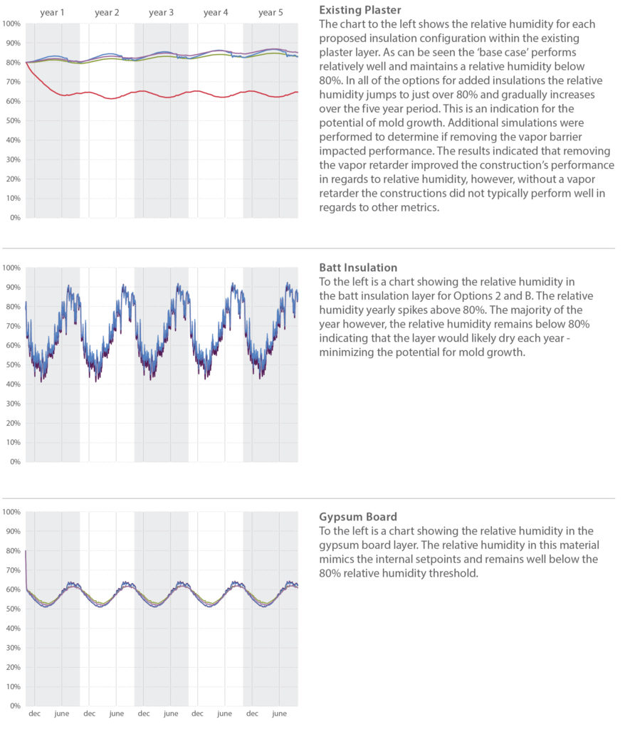
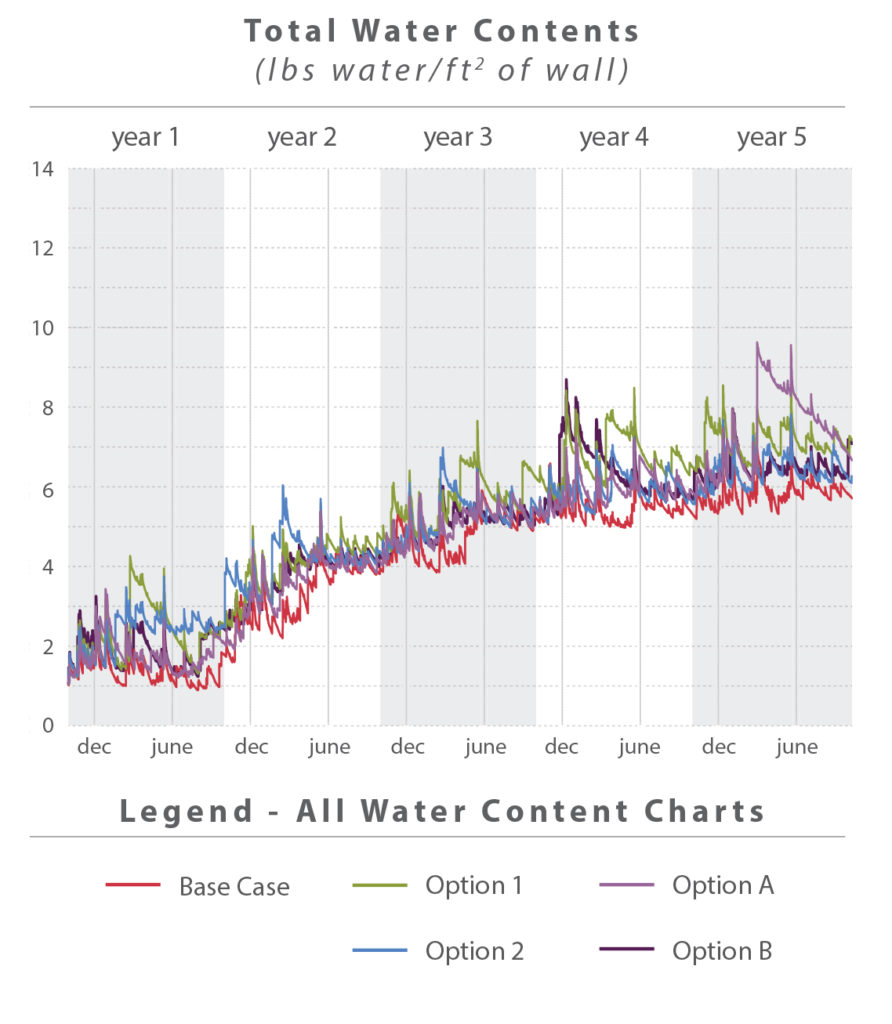
Total Water Content WUFI can predict the total accumulation of water over the time frame of the simulation, in this case five years. Over the course of each year a wall assembly will be wetted by the rain, and dry over the summer months. Differences in humidity and temperature between spaces may cause water condensation within the walls. If conditions do not allow condensation or other water to dry, materials may accumulate water over a period of time.

    The chart above shows how each of the different simulations performed. Note that total water content is measured per ft2 of wall. Walls that are thinner (existing construction) will inherently have less capacity to hold water. In general all of the walls performed in a similar manner – an indication that the retrofit strategies should perform in a comparable manner when compared to the existing walls. As can be seen in the chart, all of the simulations, including the base case showed some accumulation of water over the five year simulation. These results, however, do not conclusively show that the proposed walls will accumulate water. The results indicate that even the base case is accumulating water over time. During PMA’s site visit, however, the existing exterior walls appeared to be performing well – which would not be the case if they were consistently accumulating water. Additional analysis showed that the gradual accumulation of Total Water Content appears to be a result of initial instability within the wall construction that equalizes over time. A 20 year simulation showed accumulation over the first five years, after which the water content stabilizes.

    Water Content in Material Layers Each of the individual layers of material in a wall assembly have the capacity to hold and retain water. A high water content in any individual layer can indicate the potential for mold growth, the possibility for damage associated with freeze thaw, and a reduction in R-Value based on moisture content. Mold growth is possible when the moisture content is above 20% and if the material has the capacity to feed mold growth. The charts below show how each simulation performed for each layer within the wall.

    Water-Content-Materials-WSU-Wilmer-Davis-WUFI-Report
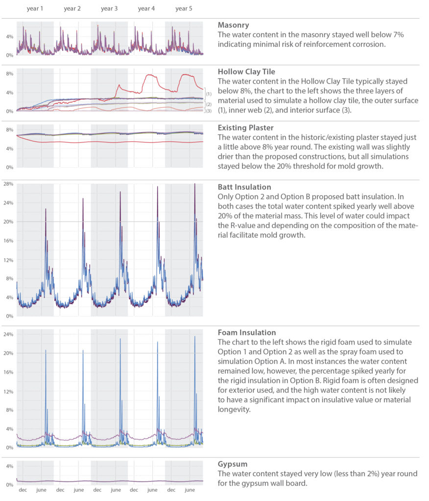
In general most layers remained well below the 20% threshold for mold growth. The insulation layers, however, are an exception. Options 2 and B both had batt and/or foam insulation which yearly exceeded 20% water. This quantity of water is somewhat concerning for the batt insulation as it may reduce the material’s R-Value and/or contribute to mold growth depending on the composition of the material. Solutions that used foam insulation performed better than those with batt insulation.

    Temperature One common result of insulating a historic building from the interior is increased freeze thaw action. Insulation prevents the interior conditioned space from heating and drying the exterior masonry. As a result the masonry is typically saturated with more water and exposed to colder temperatures. The analysis looked at the temperature within the middle of the masonry to determine how added insulation would impact the material. A chart comparing the base case to the four options for insulation is located below. As can be seen the brick temperature remains consistent with the base case in all retrofit options. This is an indication that the masonry may not by exposed to additional weathering as a result of added interior insulation. It should be noted that not all masonry reacts to water saturation and freezing conditions in the same manner. To further analyze the masonry’s susceptibility to freeze-thaw action lab analysis is recommended to determine material performance. If results indicate that the masonry is susceptible to freeze-thaw it will be critical to ensure new constructions do not lead to a significantly colder/wetter exterior wall.

    Relative Humidity The relative humidity of the air within the wall construction also has an impact on material longevity and mold potential. A high relative humidity in plaster or batt insulation layers may indicate mold growth, while a high relative humidity in layers with reinforcement may indicate the potential for corrosion. A constant and high relative humidity (above 80%) indicates the potential for mold growth. The charts to the right focus on several susceptible layers, the existing plaster, batt insulation, and gypsum board. In general the majority of the layers susceptible to mold remained below 80% relative humidity, or consistently dropped below 80% relative humidity allowing the material to periodically dry. An exception was the existing plaster layer. The addition of interior insulation caused the relative humidity within the layer to increase approximately 15%, from 65% (base case) to just over 80% (all options for added insulation). This spike in relative humidity is concerning and could indicate the potential for mold growth within the layer.
    Materials-Temperature-Relative-Humidity-WSU-Wilmer-Davis-WUFI-Report
    Isopleths WUFI can also predict mold growth by plotting isopleths on the interior surface. The isopleths are plots of the temperature and the relative humidity for every time period calculation. When the temperature and relative humidity both exceed the limiting lines calculated by WUFI there is the potential for mold growth. The simulations indicate that there is very little potential for mold growth. All of the simulations begin above the limiting lines, but over time equalize and remain well below the threshold calculated by WUFI.
    wufi-isopleths-results-wsu
    CONCLUSIONS
    The results described above indicate that there could be some challenges to designing an appropriate insulation system for Wilmer Davis Hall. Three of the primary concerns noted in the above analysis are: increasing total water content quantities; high quantities of water in the batt insulation layers; and consistently high relative humidity’s in the existing plaster layer.

    In general Option 1 and Option A performed better than Option 2 and Option B – primarily because they relied on only foam/rigid insulation. This resulted in no risk of mold growth within the insulation layers and no reduction of the R-Value. Concerns were still identified with both Options in terms of total water content and relative humidity in the plaster layer.

    Prior to detailing a new wall for construction additional analysis is recommended. Minor changes in material properties can have significant impacts on wall performance. The above analysis has indicated that there is a potential for mold growth, but has not confirmed its likelihood. Most of the metrics indicated no risk of mold growth – however because some of the metrics showed a potential for mold, additional analysis is recommended. Testing of the existing materials and specific data on proposed products should be used to refine this analysis and determine extent of mold growth risk.


    Written by Halla Hoffer,AIA, Assoc. DBIA / Associate, Architect

    Trinity-Episcopal-Church-PMAPDX-building-science

    Trinity Episcopal Cathedral Seismic Rehabilitation

    Trinity Episcopal Cathedral was constructed ca. 1904 in the Gothic Revival Style. PMA was the historic architect on the design team tasked with conducting an exterior assessment including conditions of the slate roof, flashing system, stone veneer, and other details.

    In addition, PMA studied the passive ventilation potential of the sanctuary in order to improve the space for the maximum number of occupants with the minimal cost and changes for the congregation. The original design included 10 operable dormers along the Sanctuary roof. The dormers have since been boarded over, preventing rising heat from escaping. Congregants find the space overheated during the summer months and one must question whether operable dormers would provide adequate ventilation to sufficiently cool the space. PMA developed an energy model using OpenStudio and EnergyPlus to compare the thermal comfort of occupants within the space. The study focused on the thermal comfort within the Sanctuary, and results showed natural ventilation could dramatically lower indoor temperatures during peak summer months.

    Lovejoy Pavillion 001

    Lovejoy Fountain Pavilion Rehabilitation

    Designed by Charles Moore in 1962 as part of Lawrence Halprin’s fountain sequence, the Lovejoy Pavilion represents a significant departure for Moore moving away from traditional design towards a Post Modern architectural vocabulary. This new design direction is expressed by Moore in the use of wood cribbing support columns and compound trusses resembling the surrounding West Hills of Portland, Oregon.

    Despite the copper clad roof, the wood structure was in early decay and the crib support columns were inadequate to support the roof load as visible in the crushing of support members. The structure’s Owner, Portland Parks and Recreation, committed to replacing wood components with original design, material, species, and craftsmanship.

    Building Envelope Corrections:
    • Guided Structural dismantling.
    • Created the documentation to support the replacement of deteriorated components with original species, tight grain Douglas-Fir, and improved details for weather protection.
    • Provided on-site guidance to the sub-contractor team for copper work and repair techniques.

    Old-Capitol-Point-Cloud-PMAPDX

    Old Capital Building Phase I Repairs

    The building was designed by Washington architect Willis A. Ritchie in the Queen Anne style with light gray Chuckanut sandstone. The Old Capitol Building is significant statewide for its role in both county and state government and as an important anchor building to downtown Olympia. The Superintendent of Public Instruction has been a tenet of the Old Capitol Building since 1906.

    PMA performed a leak investigation and general assessment of the circa 1892 Old Capitol Building and its 1905 East Annex addition.

    Building Envelope Corrections:
    • General exterior condition assessment of the roof systems and exterior stone.
    • Identified the potential sources of water intrusion resulting in plaster damage.
    • 3D laser scan and Revit model, the first such recording of a historic building for DES, creating a template for future assessment and facility maintenance projects.
    • Window by window condition survey.

    Marshall Wells Lofts Exterior Building Envelope and Window Repair

    The Marshall Wells property is a former industrial warehouse converted to 164 residential spaces in the heart of NW Portland’s Pearl District. Peter Meijer Architect, PC (PMA) provided a condition assessment of the exterior concrete facade and repair recommendations for the deteriorated conditions to the HOA and unit owners. PMA successfully addressed:

    • Material failures,
    • Flashing deficiencies and steel corrosion,
    • And building movement all of which have led to water intrusion.

    PMA prepared the documentation for bidding and construction; and in consultation with window contractor and the building management team, established a systematic review and assessment of butyl sealant failure of the existing windows and provided repair recommendations. Additionally, the Marshall Wells Lofts Condominium Association hired PMA to update the 2001 Preservation Plan to comply with statutes for Oregon State Special Assessment. The update includes the original Plan, annotated to indicate plan components that are completed, along with photo documentation.