Tag Archives: building envelope

Using Revit for Historic Architecture

Revit is used widely for designing new architecture and for documentation of existing structures. When first looking at Revit one may assume that it is tailored for use with contemporary designs. The default ‘Families’ (the term Revit uses to describe all types of elements from furniture to windows, doors, annotation symbols, wall constructions, etc.) are all generic to new construction. Despite the pre-set generic components, Revit’s strength lies in the ability to create custom ‘Families’ and its capability of tracking both three dimensional design as well as linked information about components. When used correctly Revit can be a powerful tool for building assessment and historic renovation. At PMA we have found several tools in Revit that can help us accurately show historic elements, track information about conditions, show repair strategies, and graphically present data.
Revit-RecordingData
When working on historic structures it can be very important to accurately show existing elements. We often need to indicate exact pieces of terra cotta that require replacement or how a stone entry stair is configured so that the cost for replacement stones can be correctly estimated. We frequently create custom ‘Families’ to accurately show historic detailing. ‘Families’ of all types can be created to refine a model and add historic detail. Some of the common custom elements that we create include windows with historically accurate profiles, stacked walls that let us show terra cotta banding and differentiation in materials/wall thicknesses, complex historic roof structures, and custom patterns that match existing stonework. By adapting the generic Revit ‘Families’ and creating our own we are able to accurately represent historic features and structures.

Capabilities
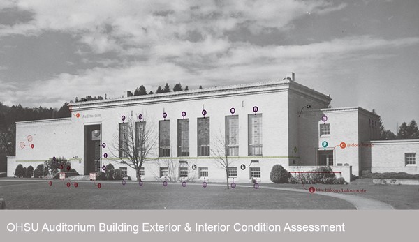
One of Revit’s most useful capabilities is its ability to record and track information about building components. Unlike earlier drafting and 3D modeling applications, Revit can store information about material finishes, specification references, and much more! In Revit you can assign ‘Parameters’ to ‘Families’. ‘Parameters’ are used in a variety of different ways – but one of the most useful we’ve found is their ability to track the condition of specific building elements. For example, when we perform window surveys we can assign ‘Parameters’ to all of the modeled windows that describe the typical deficiencies observed. For each individual unit we can then record what deficiencies were discovered in the field. Once all of the information has been added to the Revit model you can create schedules in Revit to describe the condition of each window unit and total quantities. The information can be extracted from Revit and into spreadsheet software to analyze the data, present trends, and identify repair scopes for individual units.
Revit-Filters
Using Fliter’s
Revit’s ‘Filter’s’ function is another tool that we use in conjunction with ‘Parameters’ to better understand and present information that we’ve recorded in the field. Filters allow one to alter the graphics for components based on their ‘Parameter’ values. For example we commonly use ‘Filters’ to graphically show the condition of a building’s windows after a survey. We do this by creating a condition ‘Parameter’ where a value can be assigned to each window, for example, good, moderate, and poor. We can then use filters to highlight all of the windows in good condition green, those in moderate condition yellow, and those in poor condition red. Unlike a window schedule which may require some analysis – the color coded elevations Revit can create with ‘Filters’ are easy to understand and an excellent tool for presentations.

At PMA we have found Revit to be an invaluable tool that we use day to day for a variety of uses including 3D modeling, displaying point clouds, rendering, tracking information, and presenting data. Revit is a capable tool and with a little creativity one can tailor the application to complex historic projects. The ability to create complex custom ‘Families’ that track data about the structure make it possible for our office to efficiently record, analyze, and present date we observe in the field – bringing projects all the way through development, documentation of construction documents, and construction itself.

Review our ongoing building envelope project that utilizes Revit.

Revit-PresentingResults


Written By Halla Hoffer, Associate, Architect I

PMAPDX 2015 Year in Review

HAPPY HOLIDAYS!!

PMAPDX-Holiday-2015

Wishing you a holiday season filled with cheer and delight from Peter Meijer Architect.

As we look back over the past year and reflect on our completed, on-going, and upcoming projects, we’d like to take the opportunity to say we have truly enjoyed collaborating and communicating with you.

2015 PROJECT HIGHLIGHTS
OHSU-2015-PMAPDX


Pacific-Tower-Rehabilitation-PMAPDX


City-of-LO-CRU-ILS-PMAPDX

PMA HAPPENINGS
Peter Meijer AIA, NCARB, was a Presenter at the RCI, Inc. 2015 Symposium on Building Envelope Technology. He presented on, When Field Performance of Masonry Does Not Correlate with Lab Test Results. PPS Grant High School was the case study presented.

Kristen Minor, Preservation Planner, is the newest member of the City of Portland Historic Landmarks Commission.

How to Improve Energy Efficiency in Historic Buildings

As historic architects we find window replacement projects to be particularly challenging — removing original materials from a structure can fundamentally change the design aesthetic. Our built environment must evolve to support more sustainable living, but finding the best way to achieve this goal for historic structures, while minimizing any aesthetic impacts, is an ongoing challenge.

When looking to improve energy performance the first inclination is often to replace the component with the lowest thermal resistance – the windows. Single pane historic windows provide minimal thermal resistance and contribute to heat loss through the building envelope. But is window replacement really the best option for reducing the carbon footprint of a historic building – how does it compare to other strategies?

energy-analysis-West Elevation
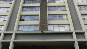
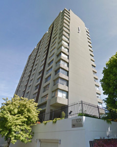
PMA recently performed an energy analysis study to answer that question. The project was to provide quantitative data on the energy savings associated with window replacement versus insulating exterior walls. We choose to study a structure on the brink of historic status – a 1960’s multi-story residential structure with large character defining view windows. The structure is composed of concrete walls, beams, floors, and columns with single pane aluminum windows. The existing building has approximately 36% glazing and no insulation.

The analysis we performed compared seven retrofit strategies ranging from minimal code compliance to super insulated walls and windows. Details on the specific constructions, r-values, and glazing properties are outlined below.

Construction Types Chart 
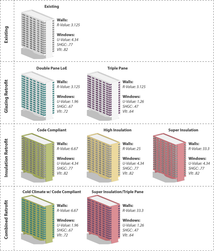
A wide range of constructions were chosen in order to see the full range of possible results. Future studies may focus on more refined material choices and a narrower set of parameters. The analysis was run in Autodesk Green Building Studio which is an excellent tool to perform basic energy models. While GBS does not allow for complex simulations it can quickly and accurately compare a variety of different design alternatives.

We chose to look at four different indicators to compare the results:
• Energy Use Intensity (EUI) indicates how much energy is used per square foot per year and is a very common way of comparing how different buildings perform.
• The quantity of electricity used per year indicates how much energy is used on cooling loads, heating loads, interior loads, and lights.
• The quantity of fuel used per year indicates primarily energy used for heating.
• The annual peak demand indicates the maximum amount of energy used at any single time over the course of a year.

We assessed the data in terms of percentage improvement over the Existing scenario. The charts below provide a comparison of the seven different retrofits.

Results Chart

The Results
What is intriguing in the results is the large difference in performance within the glazing retrofits options between the Double Pane LoE Glazing and the Triple Pane Glazing. While the Double Pane Glazing provides a notable improvement to the building’s energy performance it is still surpassed by all of the other retrofits. Conversely the Triple Pane Glazing far out performs all of the insulation retrofit strategies. The range between the two glazing retrofits indicates that new windows have the potential to have a substantial impact on energy performance. Unfortunately triple pane glazing is typically cost prohibitive and the LoE coatings applied to achieve maximum efficiency are incongruent with historic buildings. As technologies change and improve it is possible that these obstacles will be overcome – potentially making window replacement for energy efficiency purposes a more viable option.

window-detail
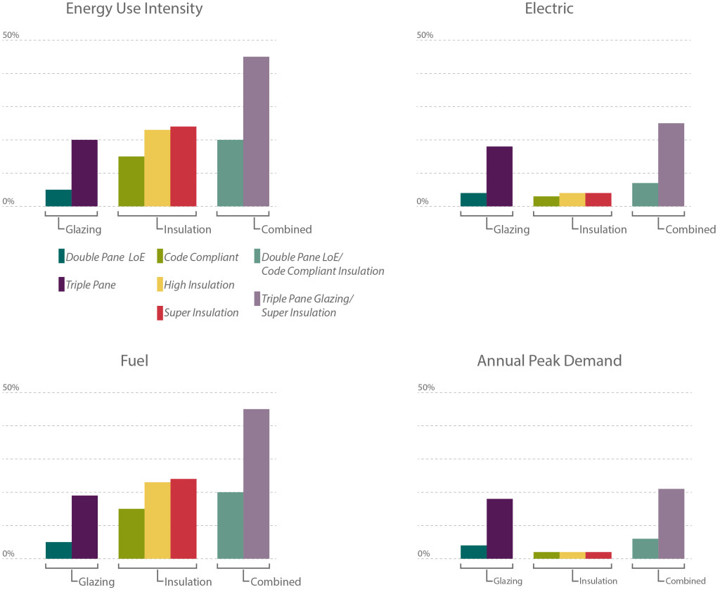
With current technologies the results indicate that adding insulation to a building has the most cost effective impact on energy performance. Installing new insulation is typically less expensive than window replacement and the results of this study show that Code Compliant (R-~7) insulation can have a significant impact on overall energy usage, outperforming Double Pane window replacement. Interestingly, the results also indicate that a High Insulation (R-25) retrofit performs better than a Combined Retrofit with Code Compliant Insulation (R-~7) and Double Pane Glass.

The results clearly indicate that adding insulation is an excellent way to improve energy performance without impacting the exterior façade of a historic building. Like any retrofit, insulation poses its own challenges: can it be installed on the interior without affecting historic finishes? Will changes in the temperature of the wall cause deterioration?, etc. Conversely, there are instances where window replacement is the right choice (when the existing windows have reached the end of their lifespan) and in this instance choosing a double pane glazing option can improve energy performance. In most cases, if you are looking to improve the energy performance of your building – it is more effective to explore insulation retrofit options rather than window replacement.

Written by Halla Hoffer, Architect I

How to Determine the Cause of Masonry Failures

Masonry-Failures-pmapdx
Visual observations are not sufficient to determine the cause of failures in masonry walls. However, visual observations, combined with technical knowledge, provide a good direction for further investigation. In the Pacific Northwest, with the predominance of rainy winter weather, the effect of moisture saturation on masonry walls is readily apparent. Moisture is the primary cause of masonry deterioration. Horizontal surfaces will accumulate organic growth, mortar and masonry surfaces show rain water runoff patterns, and any discontinuity in roof runoff systems quickly cause further deterioration to the masonry walls. Severe masonry deterioration does occur in the northwest but its occurrence is considerably less dramatic when compared to harsher winter climates in the Midwest and East. For instance, brick spalls due to freeze thaw effect are a rare occurrence in the northwest.

Masonry-Failures-pmapdx 
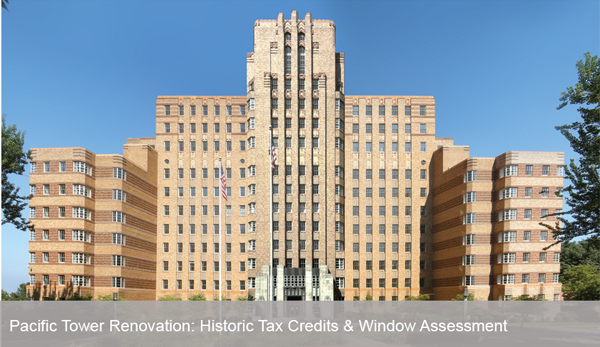
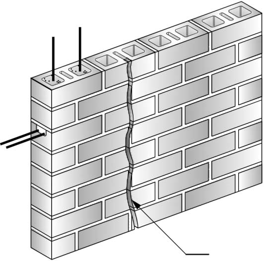
When severe deterioration of masonry walls is not a prevalent condition, what other non-visual processes are employed to determine the cause of deterioration? Two common techniques, well known to historic preservation professionals, are non-destructive testing (NDT) and material testing in the laboratory. NDE methods include RILEM tube water absorption tests, metal detector scanning, video scopes, infra-red photography, ultra sound testing, ground penetrating radar, and in some cases, x-ray diffraction. Common laboratory testing include petrographic examination, electron microscopy, and Fourier Transform Infrared (FTIR) methods.

Masonry-Failures-pmapdxFTIR, when combined with the diagnostic RILEM tube field test, in particular is an effective evaluation to determine if masonry sealers have been applied to a wall surface impeding the capillary evaporation of trapped water. RILEM tests also provide an observation of a masonry wall’s initial rate of absorption under wind driven rain circumstances. Petrographic analysis of both masonry and mortars determines the material composition and will identify harmful natural elements and harmful additive elements like salts.

Masonry-Failures-pmapdx
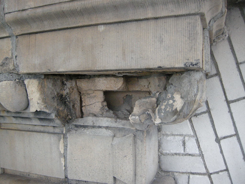
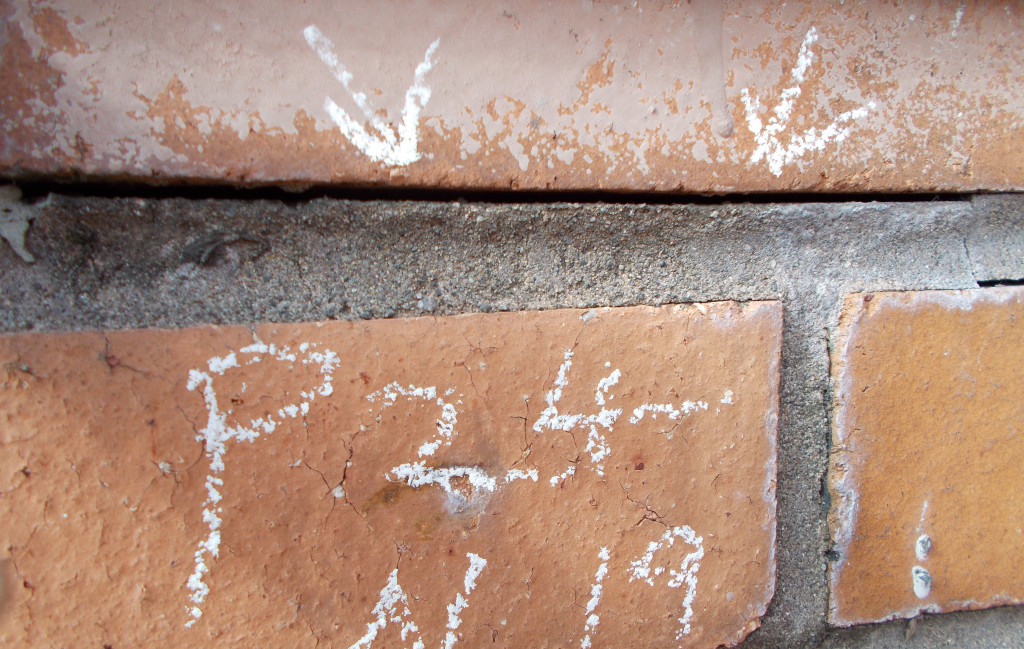
A common misconception in the northwest is that surface spalls are a result of freeze thaw cycles. Freeze thaw susceptibility can only be determined through laboratory testing. Visual observations are insufficient to conclude masonry spalls resulted from freeze thaw forces. Since freeze thaw tests are graded either pass or fail, further tests methods are typically required for additional diagnostic evaluation. More likely sources of surface spalls are hard Portland cement mortars which exceed the strength of the masonry, salts introduced into the masonry through incorrect material selection, or surface sealers impeding the evaporation of water and thus creating a saturated sub surface layer which will freeze. (It is important to distinguish that the masonry unit may not be susceptible to freeze thaw but rather the sealer creates a dam like effect inducing a layer of water subject to freezing)

Masonry-Failures-pmapdxBy combining visual observations with NDE and lab testing, most surface masonry deterioration can be determined and thereby implement proper repair, maintenance, and protection methods.

Written by Peter Meijer AIA, NCARB, Principal

PMAPDX-Meir-Frank-Building-Envelope

Meier & Frank Warehouse Renovation: Vestas HQ

Peter Meijer Architect, PC (PMA) was the Historic Preservation Architect for the full restoration of the 160,000 square-foot Meier & Frank warehouse to office conversion for Vestas Headquarters, a wind turbine developer. Built in 1928, the renovation added a penthouse with ecoroof and outdoor gathering spaces to the original four story structure. For the renovation, PMA provided:

• Building condition assessment
• Analysis for the repair and design
• Construction documents

Additionally, PMA completed a limited exterior assessment of the roof for the added penthouse at the Meier & Frank building. The deficiencies noted at the penthouse level were similar in nature to the deficiencies at the lower elevations. The building is LEED platinum.

The Meier & Frank [Warehouse] built in 1927, was designed by the noted Portland architectural firm of Sutton and Whitney. The restoration of the Meier & Frank Warehouse required the evaluation and repair of extensive concrete cracking, replacement of reinforcing bar, and detail drawings suggesting the construction of repair concrete form work.

PMAPDX-oregon-State-Capitol

Oregon State Capitol Building Fire Restoration

The Oregon State Capitol was designed by the New York architectural firm of Trowbridge and Livingston in association with Francis Keally and completed in 1938. Erected in the Modernistic style, the Capitol was sensitively enlarged in 1977 by the Portland firm of Wolff Zimmer Gunsul Frasca in association with Pietro Belluschi. Constructed of reinforced concrete, the building is distinguished by angular, unadorned exterior elevations and a massive, ribbed lantern all sheathed in brilliant white Vermont marble.

In 2008, as part of the team creating a new Master Plan for the Capitol, PMA conducted a full exterior condition assessment of both the main building and east and west wings. On Labor Day 2008, an exterior fire damaged the Vermont marble and Oregon walnut interior panels adorning the Governor’s Ceremonial Suite. PMA was retained to guide the faithful restoration of this important Oregon icon.

Due to the third fire in the Oregon State Capitol’s history, the Governor’s Ceremonial Suite required complete restoration and renovation. PMA provided restoration documents for the repair and replacement of exterior marble, repair of interior walnut paneling, reinstallation of linoleum flooring, reintroduction of historic carpet, integration of preservation of historic materials, and the repair of plaster ceiling and walls. Additionally, PMA provided guidance to the conservationists repairing the WPA painting, which was also damaged. All restoration work was based on historic research and field analysis of existing materials.

Horizontal Ground Motion: A Call for More Seismic Research

There is a lack of significant research and seismic performance studies on the resiliency and inherent strength redundancy of older buildings.

U.S. Post Office & Courthouse, 7th & Mission Streets, SF

U.S. Post Office & Courthouse, 7th &; Mission Streets, SF

In specific, the capacity of existing buildings to resist ground motion associated with earthquakes has not been fully developed or thoroughly researched. Based on damage from earthquakes, especially the 2010 Canterbury and 2011 Christchurch earthquakes in New Zealand, with additional seismic activity lasting nearly one year, the general thought is that older existing buildings perform poorly in response to ground motion. When analyzed further, the damage from the Christchurch earthquake was predominantly due to acceleration in a vertical direction, literally tossing buildings in to the air. The peak vertical acceleration during the Christchurch earthquake exceeded the design criteria for today’s modern buildings. Not lessening the severity of the event, nor proposing for less stringent seismic codes, the Christchurch earthquake would flatten most modern cities regardless of building age. Adequate resistance to vertical movement cannot be achieved with current engineering techniques and therefore research and performance studies regarding the resiliency of existing structures must concentrate on horizontal ground motion.

1906 earthquake, Montgomery Street block, SF

1906 earthquake, Montgomery Street block, SF

Because little can be done to prevent building collapse during vertical motion, seismic strengthening techniques focusing on dampening and resisting horizontal motion are applicable to existing structures as well as new structures. However, there has not been significant studies documenting and establishing the inherent strength to resist horizontal motion due to redundancy and mass of archaic construction methodologies. Independent performance evaluations of unique structures have occurred in the United State, Italy, Mexico, the Baltic, and others regions around the world without formal comparative analysis of the results or thorough in-depth dissemination and publication of the studies. For instance, in Oregon, informal static shear testing of a circa 1925 public middle school’s interior fire block and plaster wall surprised structural engineers when the walls did not crack at the shear planes (i.e. floor and ceiling connections) and strength measurements exceeded code allowance fivefold. (2001 Portland Public Schools shear test) When calculated and tested, the ½ inch chalk boards added even more in-plane horizontal resistive strength. The result of the testing saved the school district approximately $ 1 million in seismic upgrade costs. There was no formal documentation of the result and there has been no known similar testing performed on other existing school properties.
mosque
The seismic resistance of existing structures is affected by the structural typology, the construction materials, the varying modifications, and deterioration and decay of materials over time resulting in unique conditions that are not readily transferrable to other structures. However, sporadic investigation and research performed on existing structures and published by the international RILEM Technical Committee 20 TBS in the article “Specific recommendations for the in situ load testing of dwellings and of public and industrial building structures,” and published accounts of independent studies in journals such as the Association of Preservation Technology Bulletin offer insight into the potential redundant strength capacity of existing structures to resist horizontal ground motion.

full scale shake table
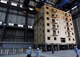
These studies combined with documented field assessments and field evidence of older structures surviving earthquakes and repeated ground motion disturbances over several hundred years are available in numerous communities and offer case study structures for further research. The numbers of university engineering departments with “shake tables” (e.g. Portland State University) create opportunities for joint partnership with private sector consultants, public agencies, and professional organizations to assess and analyze the unique aspects of archaic building materials and methodologies for seismic response. The collaboration between university and private cooperation for seismic research has the potential to develop a wealth of practical and applicable information. The current collaborative efforts involving energy consumption offer the model from which to base seismic research.

A development of systematic research, publication, and dissemination of the inherent strength of existing structures to resist horizontal ground motion would benefit all communities across the globe.


Written by Peter Meijer AIA, NCARB, Principal

Burnt Clay Facades

Terra cotta, or “burnt clay,” is a hard baked, high grade of weathered or aged clay. It is similar to brick but the clay is of higher quality and fired at higher temperatures. This article focuses on exterior architectural terra cotta as distinguished from statuary, pottery , and terra cotta blocks used as inner wythes of wall or fill material.
300px-Court_of_Honor_and_Grand_Basin
The 1893 Columbian Exposition in Chicago demonstrated the versatility and ornamental qualities of terra cotta. It highlighted the great variance in color and shapes possible with terra cotta and began the demand in the United States for terra cotta that lasted through the late 1930s. Terra cotta is prized for its light weight, longevity, aesthetic qualities, and unit construction. At the peak of production, almost every urban area in America was producing architectural terra cotta in some variation. Today, most replacement units are produced by either Gladding McBean or Boston Valley Terra Cotta.

Specific forming techniques including hand press, machine press, slip casting, and extrusion are used depending on the shape and style of unit required. In the analysis of terra cotta failure the forming techniques are less critical than the strength characteristics of the fired clay, the integrity of the exterior surfaces, and structural support systems.
Boston Valley new TC
Exterior ornamental terra cotta was marketed as a light weight water proof cladding. And if proper construction techniques were employed, and the system was maintained, and the local climates were mild, terra cotta performed as sold. However, terra cotta adorns buildings in severe weather climates, and is installed with structural materials affected by environmental conditions, and located on façade elements inaccessible for routine maintenance.

The mortar joints are the material most susceptible to failure. Joints often exist on all three axis with some units of terra cotta designed for flat horizontal surfaces. Over time and exposure, the mortar fails providing a means for water intrusion. Sever cycling of weather in simultaneous freeze/thaw conditions can cause the terra cotta clay to expand and contract, accelerating the crazing or cracking of the protective glaze. Extensive crazing can lead to glaze spalling and allow for further water intrusion.

Once water enters the system there is no weep path allowing for water egress. Construction means and methods, as well as the cellular unit design, trap water and contribute to the potential corrosion of steel lintels, wire ties, steel structural support members, and other miscellaneous metals. Rapid freezing and thawing cycles, in addition to steel corrosion, can crack terra cotta units. If the units remain unrepaired, further water intrusion and/or absorption will occur.
121022 QAHS S Elev 094
The repair of terra cotta will depend both on the cause and manifestation of the defect. Typical defects include crazing of the glazed finish, shallow surface spalls, deep spalls affecting the bisque, cracked units, inadequate support and / or anchorage, corrosion induced stress fractures, impact damage, mortar degradation, lack of maintenance, and inadequate repairs.

Proper terra cotta repair methods are linked to the cause of defect. Repair techniques are often performed on-site by skilled tradesmen. When damage to the terra cotta unit is severe, full replacement may be required. Defects due to inadequate support or a result of corrosion to supporting steel members is likely to require more invasive repair strategies including removal and replacement of several courses of interlocked terra cotta units.

QAHSC
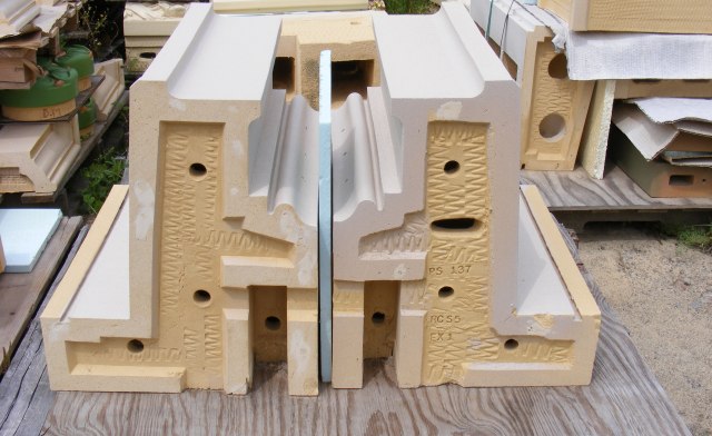
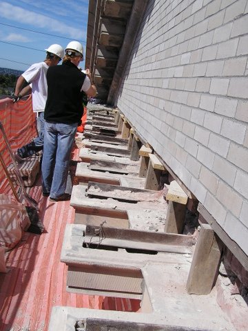
When replacement units are not required and the scope is limited to on-site repair, labor costs exceed material costs. Since many historic terra cotta units were specialty designed and installed for the structure, a premium price is paid for replacement. New exterior decorative terra cotta is available only from the sources referenced and with small quantity orders, the first unit is approximately $5,000 with much of the costs attributed to making the form and determining the finish color and texture. Subsequent costs per unit will decrease with the range of decrease dependent upon quantities required.

The most important component of terra cotta repair is an understanding the cause of deterioration and the proper repair specifications. Both are derived after a full condition assessment and evaluation of the existing conditions.


Written by Peter Meijer AIA, NCARB, Principal


——————–
Sources
• Last of the Handmade Buildings, Virginia Guest Ferriday, Mark Publishing Co., Portland, OR 1984
• National Park Service, Preservation Brief No7, Preservation of Glazed Terra Cotta
• APT Pacific NW Chapter 2005 workshop
• Terra Cotta, Standard Construction, Revised Ed., National Terra Cotta Society, 1927

The Challenges of Assessing Structural Brick Veneer Panels

The origin of Structural Brick Veneer Panel dates back to the early sixties when new “tensile strength intensive” exotic mortar combined with steel reinforcing to create a 4-inch thick, single wythe brick panel. Developments continued to occur throughout the 1960s and 1970s, peaking in use during the 1980s. The system was relatively expensive due to the use of the high tensile strength mortar.
Koin Center brick pane
Developments in both the high tensile strength mortar and the clay units continued to reduce cost and allow the use of regular reinforcing and standard mortar and grout. Newer systems and manufacturing processes accommodated both horizontal and vertical reinforcing and permitted high-lift grouting. Later advancements in the connections of the brick veneer panel system to the building frame resulted in the use of brick veneer panels system on multi-story high-rise office buildings, schools, apartment buildings, residences and many other applications throughout the United States and the Pacific Northwest.
cracked brick_design guide
Major Failure Mechanisms
There are two major failure mechanisms of Structural Brick Veneer Panels: water intrusion and mortar/grout additives. Water intrusion can occur from a lack of adequate flashing at the window head and sill interface, carbonization of the mortar, and structural cracking. Brick veneer panels are commonly designed to allow for limited cracking at the horizontal bed joints at the brick to mortar interface. Masonry veneer panels leak more through the mortar and brick interface than through the masonry unit itself. If the mortar and brick interface is cracked, as is permitted under structural design calculations, water infiltration will increase. A cement based material, panel mortar will carbonize over time decreasing the protective alkalinity environment surrounding the reinforcing bar and thus increasing the potential for corrosion. The largest volume of water intrusion is typically associated with inadequate window systems that fail to keep water out of both the structural brick veneer panel and the cavity interface.
024
The durability of the wall is highly influenced by the quality of the mortar joints and interior cell grout. The specification should require reconsolidation of the grout or the incorporation of additives that balance expanding, retarding, and water reducing agents to provide a slow, controlled expansion prior to the grout hardening. Mortar/grout additives, particularly those developed in the 1970s, containing vinylidene chloride can initiate and accelerate reinforcing steel corrosion under the right conditions. The composition of the mortar/grout is determined through laboratory analysis of chloride content, vinylidene chloride, and pH level.

Repairs to structural brick veneer panels is labor intensive and may involve panel replacement, panel encapsulation, window system replacement, and/or extensive individual masonry unit repair.


Written by Peter Meijer AIA,NCARB, Principal
—————

Acknowledgement: Tawresey, John G. & John M. Hochwalt, KPFF Structural Engineers, Design Guide for Structural Brick Veneer, 3rd Ed, Western State Clay Products Association

Water Intrusion: The Technique of a Leak

With patience, persistence, and a methodical process, water intrusion defects can be
located and repaired.

Finding the source of water intrusion within an older existing building can be exceedingly frustrating. Following a methodical and systematic investigation procedure will manage and organize the process. If the leak is occurring within occupied space, it is critical to interview and obtain information from those individuals directly affected by the circumstance. Is the leak associated with weather, water use, or other activities? If weather related, when did the leak occur relative to the start of the bad weather? Does the leak occur under windy conditions only? Wind driven rain can push water 2 inches up a vertical surface. Does the leak occur consistently in the same spot? Having an understanding of the building’s age, material science, archaic construction techniques, and professional experience brings focus to the investigation.
MW Loft water intrusion PMAPDX
Visual observation is the single most important diagnostic tool. Are there obvious sources of water intrusion like open windows, broken downspouts, exterior holes in the building shell, or leaking bathroom fixtures? Storm days are often good opportunities to observe the flow of water over a building surface leading to potential sources. After a rain storm, are some exterior surfaces slower to dry? Has the water pooled along horizontal surfaces or against exterior walls? These observations can be made directly by the investigation team or related by maintenance personnel or property owners. Photographs taken before, during, and after a leak provide valuable perspective on the dynamic nature of the leak.

Infaread testing
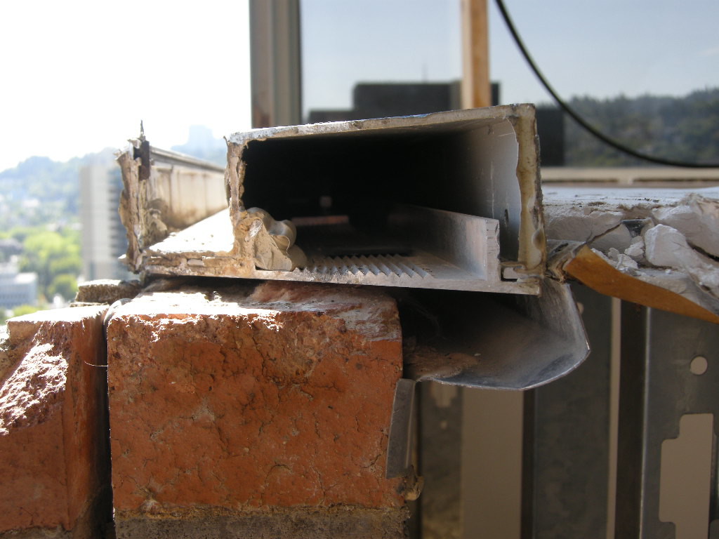
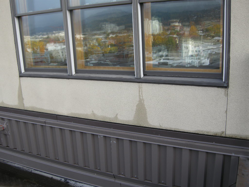
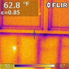
Infrared camera analysis adds another diagnostic layer of evaluation data. Temperature differentials between wet and dry surfaces can collaborate other visual observations. However, a number of varying conditions, not just water, can cause temperature differences between materials or even temperature differences within the same material. For instance, an exterior stucco wall installed over steel studs may have extreme temperature changes as a result of heat conductance through the steel studs with no related water intrusion.


Often it becomes necessary to augment general observations of interior and exterior surfaces with destructive investigation, a method by which the surface materials are sequentially removed to investigate archaic construction methods. As materials are removed, construction techniques can be evaluated for water tight joints. Moisture meters and other hand-held evaluation tools verify the presence of defective conditions. Openings, or wall-lets, are located at corners, abutting materials, complex intersections of structural elements and architectural materials, and/or other commonly known sources of water intrusion.
MW Loft Stucco repair PMAPDX
Reverse investigation in which the leak point is enlarged and video scopes or wires or other tracing devices are inserted in the opening are used to back trace the leak from the point of observation to the source. This method is often a last resort because it involves cutting several observation points in all directions to follow the path of water.


Written by Peter Meijer AIA,NCARB, Principal