Tag Archives: masonry

Project Update: Fountain Place Apartments

Progress photos from our Fountain Place Apartments project for Home Forward

Part of extending the operational life of this existing and historic building is a seismic upgrade. Pictured is the opening up of the floor structure on Levels 1 through 5 to facilitate the installation of a new central egress stair and elevator, which will support accessibility to all levels of the building and provide additional means of egress. Two of the six proposed braced frames will be installed adjacent to this elevator and stair. The braced frames are supported by piles at the foundation and will be tied to a new plywood diaphragm at each floor and the roof which will provide most of the seismic stability required for the building, affording structural safety to future occupants and ensuring the life-cycle of this historic building is extended for another 50+ years.
fountain-place-apts-home-forward-renovation

fountain-place-apts-home-forward-renovation
SECRETARY OF THE INTERIOR STANDARDS
The project is meeting the secretary of the interior’s standards for redevelopment, reviewed and approved by the Oregon State Historic Preservation Office and the National Park Service. Federal tax incentives were used, and as part of the process the building was listed on the National Register of Historic Places.
fountain-place-apt-home-forward-renovation
LEARN MORE ABOUT THIS HISTORIC AND SEISMIC UPGRADE PROJECT
To learn more about how our team is reviving a historic building by providing critical infrastructure for current residents and new arrivals, please visit: Fountain Place Apartments.

fountain-place-apts-seismic-bracing

Written by Kate Kearney, Associate, Marketing Manger

Building Insulation and Historic Masonry Structures at APTNT2020

The proper application of building insulation for historic masonry structures is a hot topic in the world of heritage conservation. Owners of historic residential, commercial and institutional masonry buildings have the unique challenge of how to maintain these structures with the latest building technologies without compromising any historic character.

As a topic we routinely discuss solutions for with our clients, we are excited to share Daniel S. Castele, Architectural Conservator & Designer, Peter Meijer Architect, PC, will be presenting at HINDSIGHT 2020 on: Insulating the interior face of historic masonry building envelopes in cold climates: a review of prescribed techniques and pitfalls.
pmapdx-apt2020
The Association for Preservation Technology & the National Trust for Canada have partnered to present, HINDSIGHT 2020 (October 1-7, 2020), a fully virtual conference, that will explore the role of heritage conservation in the 21st century. Leaders within the architectural, engineering, construction, preservation, conservation, policy, and design communities, will present on the intersection of heritage conservation and technical, design, policy and community issues.

DAN’S PRESENTATION AT A GLANCE
The need to insulate walls of historic buildings to meet ambitious energy performance targets has been a rising concern in the preservation community. Due to preservation code and accepted best practices, it is not viable to add insulation to the exterior of an existing historic building. In response to this a common approach is to insulate the interior face. While this method of wall insulation can significantly reduce heat loss and improve thermal comfort in cold climates, it also raises concerns about damage to historic fabric. This study examines the current guidance available to project teams. Publications from North America and Europe have been systematically reviewed for guidance on retrofit techniques and evaluation methods. The study reveals a wide range of both prescriptive and performance-based recommendations.

This presentation will explain the progressive research behind a comprehensive and in-depth study of guidelines and professional practices related to internal wall insulation retrofits in historic buildings of North America. The study is part of larger ongoing research into net zero historic buildings. For which, the presenters single-handedly collect and review guidelines for trends, similarities, and differences. The presentation will be based both on research gathered from other professionals and first-hand experience and research conducted by the presenters themselves.

KEY LEARNING OBJECTIVES
Explain the issues, risks, and benefits associated with insulating the interior envelope of mass masonry walls of historic structures; Discuss insulation approaches for masonry envelopes offered in existing guidance from the preservation community and government whitepapers; Discuss commonly used wall insulation details in practice in Canada, USA, & Europe; Compare performance-based approaches and prescriptive recommendations.

To learn more about the conference and to register, please visit: HINDSIGHT 2020.

History of Fountain Place Apartments, formerly Wheeldon Annex

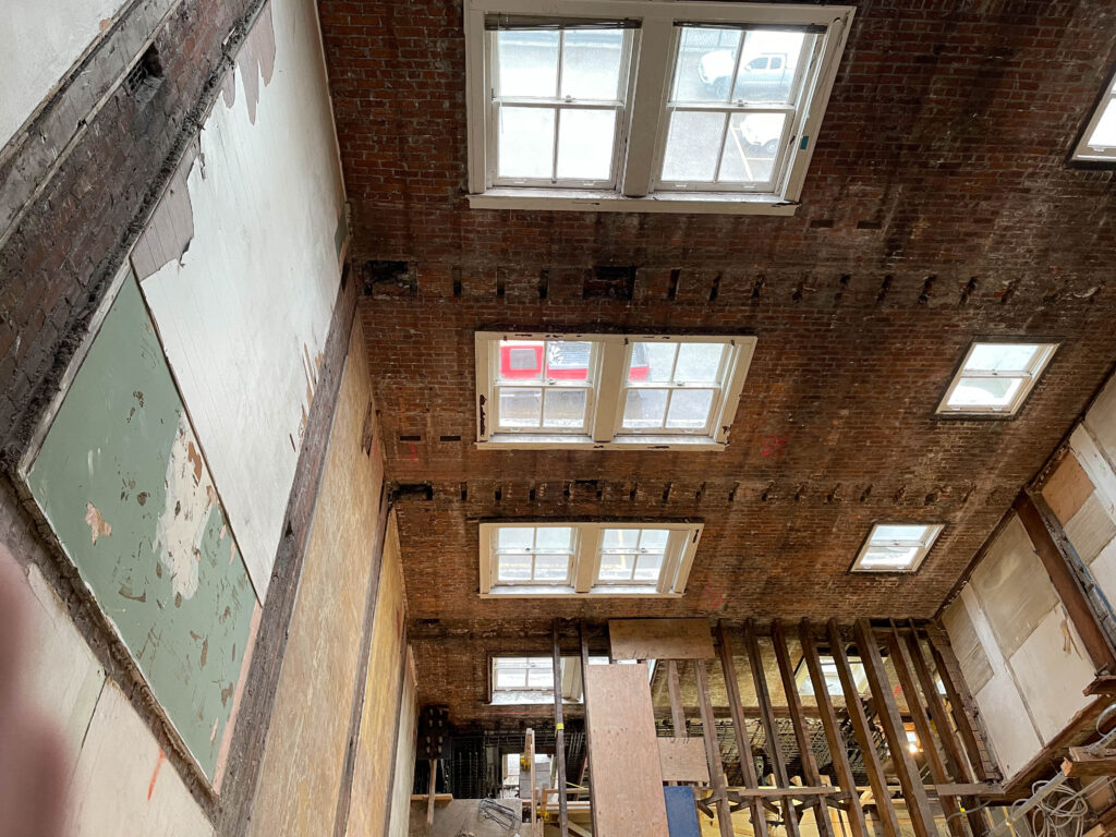
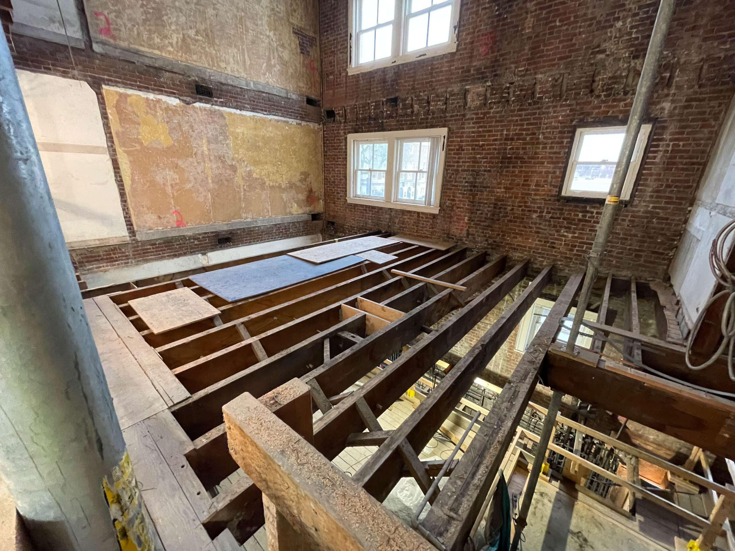
Back in April, we introduced an exciting on the boards project – Fountain Place Apartments Seismic Upgrade. Working with Lorentz Bruun Construction, we are delivering a design-build project to improve the life safety of Fountain Place Apartments, while retaining its historic character. Completed in 1914 and originally named Wheeldon Annex, Fountain Place is a five-story unreinforced brick apartment building located in downtown Portland, owned and operated by Home Forward. There are 74 total units, with studio, one-and two-bedroom homes. The unit mix is 5 at 40%, 5 at 50% and the rest restricted at 60% area median income (AMI). While the project is progressing on schedule, we will be discussing below the architectural significance of this historic resource as it relates to our built environment.
historic-1916-fountainplace-wheeldon-annex
OVERVIEW
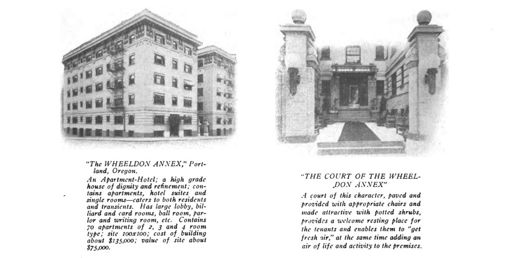
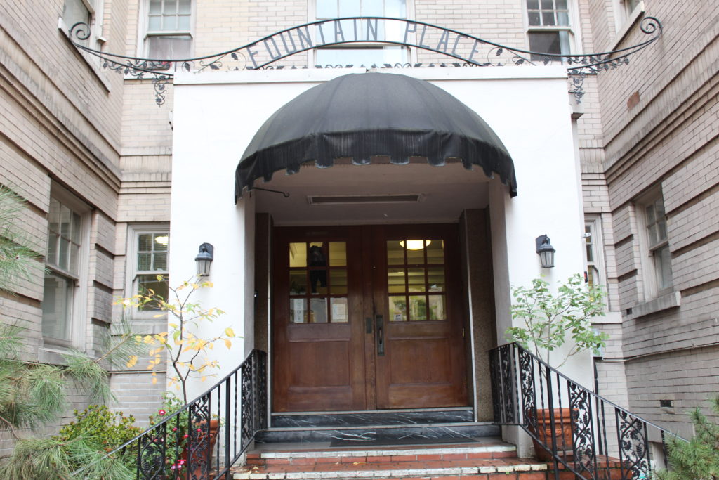
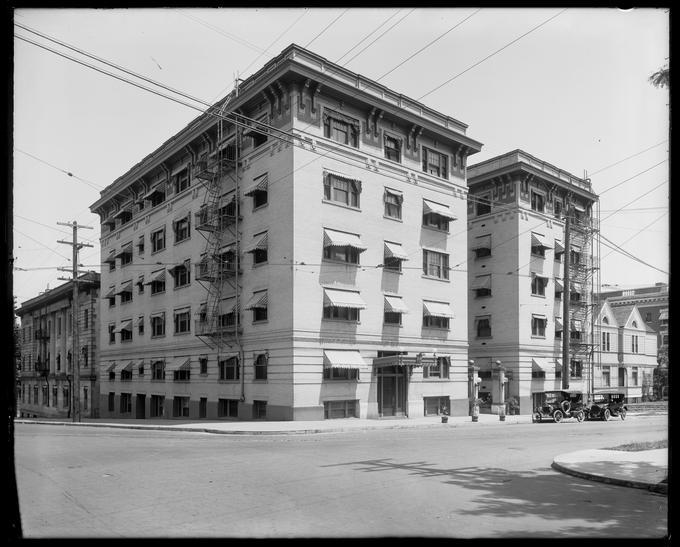
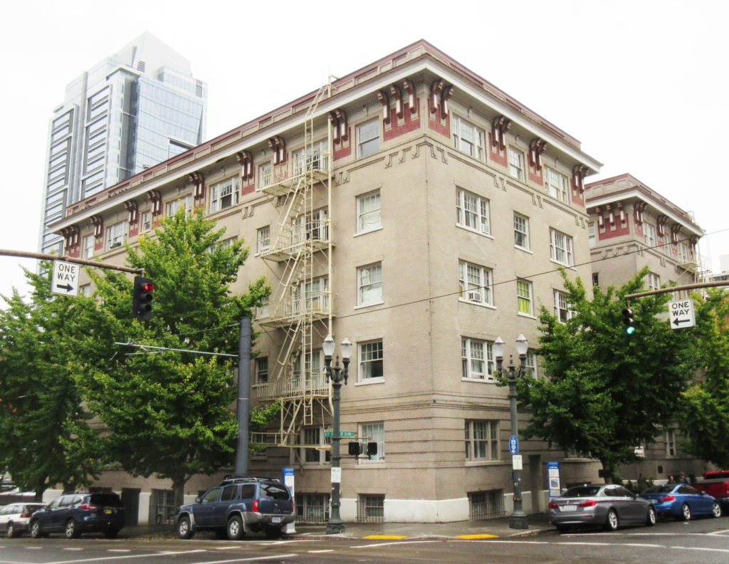
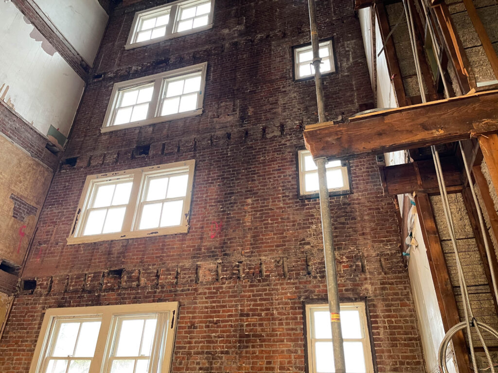
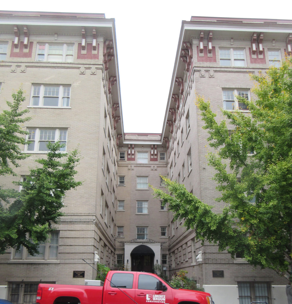
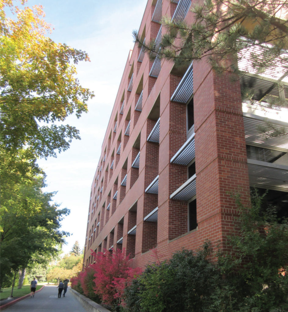
Constructed in two distinct phases in 1911, the Fountain Place Apartments were originally named the Wheeldon Annex. The building occupies a quarter-block lot in downtown Portland, Oregon, at the corner of SW Salmon Street and SW 10th Avenue. The Wheeldon Annex is one of the earliest surviving examples of a U-shaped residential apartment/hotel in downtown Portland. It is a 5-story brick structure with intact Italian Renaissance Revival features such as a decorative bracketed cornice, buff brick body with corbeled details and rusticated base, and an upper level treated as a paneled frieze. Character-defining wood double-hung multi-pane windows have been retained throughout and appear to be well maintained. Alterations to the exterior have been quite minimal.

The interior of the Wheeldon Annex has good integrity; although a number of units have been altered or divided, the general layout with U-shaped double-loaded corridors at every floor remains, and many units still contain at least some original features, materials, and layouts. These include primary rooms with original oak flooring and in some cases, the original built-in furniture with pull-out beds and fold-down desks; kitchens with wood cabinetry and trim; and bathrooms with claw foot tubs and built-in ventilation and cabinetry. While there are many units that have been divided, the alterations (primarily in the mid-1930s but continuing into the 1990s) have generally left original features in place.
detial-fountain-place-home-forward

The history of Wheeldon Annex is engrained in Portland’s and Oregon’s social history and practice of systemic racism. From Oregon’s statehood in 1859, the Black population were marginalized and segregated from the White population. Oregon’s State Constitution included Article 1, Section 35, “No free negro or mulatto not residing in this state at the time of the adoption of this constitution, shall come, reside or be within this state or hold any real estate, or make any contracts, or maintain any suit therein.” With the 14th and 15th Amendments, in 1868 and 1870, respectively, the Article should have been nullified, but the practices within restrictive covenants, discriminatory real estate sales, and racist zoning practices overwhelmingly prevented Black people in Oregon from accessing jobs, housing, and other vital resources.

In 1910, one year before Wheeldon Annex opened, the Black population in Oregon was 1,492 while the state’s total population was 672,765. In Portland, the Black population was 775 while the city had a total of 90,246 inhabitants. The legal and systemic provisions put in place by the White majority were working to the detriment of Black people in Oregon.

DESIGN OF WHEELDON ANNEX
When Ernest MacNaughton was commissioned to design an apartment building for Frank Warren, he would have been quite familiar with the large apartment blocks built for well-off tenants on the east coast. MacNaughton’s design for the 1911 Wheeldon Annex illustrates a residential apartment block form with front courtyard protected on three sides. This form created an outdoor area but with restricted access, a pragmatic response to the more urban condition in downtown Portland.

The Wheeldon Annex, with its front entry court, appears to be among the first buildings in Portland to use a residential apartment typology in the downtown setting. There are only two earlier examples of a U-shaped apartment-style building constructed closer to downtown than those listed above; one of these is now demolished: the 1910 Beaux-Arts style Rose-Friend Apartments at 1307 SW Broadway. The other comparable downtown example pre-dating the Wheeldon Annex is the 1908 Nortonia Hotel (now Mark Spencer Hotel) at 409 SW 11th Avenue. The 6.5-story building was designed by Josef Jacobberger and has, atypically for a hotel, individual rooms along the ground floor rather than storefront with more commercial or public uses. The building exhibits a U-shaped plan with a central front pedestrian entry court and has a restrained style, with some Tudor elements and some Italian Renaissance Revival decorative touches. It is worth mentioning that there was another much larger but well-known hotel that may have been inspirational in its massing and layout. The opulent full-block Portland Hotel, which opened in 1890 and was demolished in 1951, was a 6-story building with H-shaped plan including a large forecourt for carriage drop-off.
fountain-place-home-forward
SIGNIFICANCE
Designed by MacNaughton & Raymond for owner Frank M. Warren, the Wheeldon Annex is locally significant for its illustration of the newly acceptable, and even fashionable, shift towards high-end residential apartment living in downtown Portland. The building is one of the earliest downtown examples of a U-shaped residential apartment block form, which later proliferated across Portland, including in the downtown setting. It was completed in 1911, using a U-shaped layout first seen as early as 1907 in high-class apartments in the exclusive “Nob Hill” residential district to the west of downtown Portland. The Wheeldon Annex is associated with Portland’s exponential growth during the ten-year period starting with the Lewis and Clark Exposition. During this time, apartment buildings were introduced in Portland as a new type of construction and use targeted towards the wealthier class.

The Wheeldon Annex is also locally significant because it is a highly intact work of the well-regarded Portland architectural partnership of MacNaughton and Raymond. The building displays distinctive characteristics of the Italian Renaissance Revival style in its division into three parts; the rusticated base, middle, and decorative cornice. The Wheeldon Annex was conceived as a high-end venture; and its use of modern built-in, fold-away furniture, single bathrooms for every apartment, dumbwaiters, and tenant services gave the building a highly respectable and up-to-date reputation as soon as it was completed in 1911. While not all of these interior features, especially in individual units, are still present, the building still has good integrity overall. The building is still in its original and primary residential use, although it no longer has “hotel” functions. The building maintains its original location, design, setting, materials, and workmanship and still conveys its overall historic feeling and association.
1920-wheeldon-annex-oregonian
The incredible boom in apartment and hotel construction in the first decade of the 20th century in Portland took place primarily in downtown and in northwest Portland. What is significant about the Wheeldon Annex is that it was one of the first to take the new apartment building block form, the largest and newest residential typology, and put it downtown without any ground floor commercial or significant public uses. Rather, the building featured a residential-style front courtyard. Almost all earlier forecourt apartment block examples in Portland were located significantly west of downtown. The Wheeldon Annex was constructed as an apartment-hotel, offering limited services to guests who might be permanent or temporary.

The building is locally significant for its association with the period of explosive growth starting with Portland’s Lewis and Clark Exposition in 1905. It is one of the earliest existing representations of a building typology that was to become all but ubiquitous. The size, scale, and general footprint of the building spawned hundreds of structures across Portland using a similar size, scale, and front court entry well into the 1930s. The building was designed by MacNaughton & Raymond for Frank Manley Warren, a man who made his fortune in the salmon packing and canning industry and died on the Titanic in 1912; one of only two Oregon residents to perish in the disaster. The building design features highly intact Italian Renaissance Revival exterior features such as a projecting decorative cornice with grouped brackets, a rusticated brick base, and multi-pane wood double-hung windows. It is therefore also locally significant for its architecture; as a well-crafted example of the style by a highly regarded Portland architectural firm.
HF-Fountain-Place-PMAPDX-LBC
MACNAUGHTON & RAYMOND ARCHITECTS
Ernest Boyd MacNaughton was an architect in Portland who practiced successfully for several decades. However, he also succeeded in becoming, through his own efforts, one of Portland’s powerful and influential banking and civic leaders. MacNaughton was born in Cambridge, Massachusetts, in 1880. MacNaughton arrived in Portland and was employed by Edgar M. Lazarus for three years until he formed his own office in 1906 with his brother-in-law, Herbert Raymond, an engineer. In 1907, only a few years after he had arrived in Portland without appreciable money or family connections, MacNaughton began to make speculative real estate transactions, riding the incredible growth in land values at that time in Portland.

In 1913, E. B. MacNaughton’s reputation took a hit when he was fired by Henry Pittock, publisher of the Oregonian. MacNaughton had been hired to renovate the Marquam building at Sixth and Morrison, but the east wall of the building collapsed when renovations were attempted and the building ultimately had to be demolished. By some accounts, the building was poorly constructed with defective materials.

By 1928, MacNaughton became involved with the First National Bank of Portland. He became president of the bank in 1932, and by 1947 chairman of the board. MacNaughton also sat in a position of leadership with many Portland institutions.

Across his design career, MacNaughton’s work shows an excellent sensitivity to scale and composition and a propensity towards a muted, 20th Century Commercial aesthetic perhaps most evident in his later warehouses. He did not have his classmate and early partner Ellis Lawrence’s facility with asymmetrical compositions or charming English styles, but MacNaughton showed a more than competent talent for the design of urban, commercial structures. Many of his buildings use tripartite “Chicago” windows, and almost all are brick.


Written by PMA staff, edited by Kate Kearney, Associate, for clarity.

On the Boards: Fountain Place Apartments Seismic Upgrade

HF-Fountain-Place-PMAPDX-LBC

Built in 1914 and originally named Wheeldon Annex, Fountain Place is a five-story unreinforced brick apartment building located in downtown Portland, owned and operated by Home Forward. There are 80 total units, with studio, one and two bedroom homes. The residents it serves have incomes between 40% and 80% of the area median income. The building is listed in the City of Portland Historic Resource Inventory, with an III ranking for its architectural significance. Fountain Place was built in the Second Renaissance Revival style with a raised basement, bracketed sheet metal cornice, and belt course with brick corbels. The building has a basement and courtyard. Presently, PMA is working with Lorentz Bruun Construction on a design-build project to improve the life safety of the building, while retaining its historic character.

Within the need for seismic upgrade lies a number of challenges our team has the solutions to resolve. Seismic upgrades within historic buildings are disruptive to existing electrical systems, mechanical systems, plumbing systems, and impact existing resident walls and units. The design-build team understand the challenge of minimizing the disruption and how to navigate current City of Portland URM retrofit standards as they relate to potential future mandates for these types of buildings.

While the project is in its preliminary stages, the team has reviewed the existing conditions at Fountain Place, including the extensive previous documentation and visited non-occupied spaces within the building. Up next for the team are additional investigations into the existing conditions that go beyond research and visual observations.

FOUNTAIN PLACE TEAM
Lorentz Bruun
Peter Meijer Architect
KPFF
Reyes
GLUMAC
Salazar Architect, Inc.

HF-Fountain-Place-PMAPDX-LBC

Post-Modern Higher Education Facility Assessment

BACKGROUND
Construction means and methods of masonry veneer walls, and particularly flashing systems needed for protection from water intrusion of those veneer walls, was well known in the Post-Modern era (circa 1980’s – 1990’s). Many professional organizations and industries (e.g. Brick Institute of America) published technical documents as guides to proper construction of masonry veneer walls.

PMA was retained to conduct a building envelope enclosure assessment of a Post Modern masonry veneer building, over the Owner’s concern of advanced deteriorated conditions of precast window sills. The purpose of the assessment was to provide the Owner an understanding of the extent of the precast failures, whether or not any other materials were impacted by the failed conditions, and to provide an analysis of potential cause and a rough order of magnitude cost of potential mitigation. The Owner also sought an evaluation of the effectiveness of a proposal to install sheet metal over the sills to prolong the life of the precast for another forty years.
PoMo-EME-Building-Assessment-WSU
The circa 1984 Post Modern masonry veneer building links two existing historic academic classroom buildings and functions as both laboratory space and faculty offices. The building is an off-set “T” in plan with the leg of the T forming the link between the existing academic structures. A six-story faculty office tower, rises between the existing structures on the east end of the leg. The majority of the window openings occur along the bar of the T on the west elevation. The building wall cross section, from exterior to interior, is comprised of a single course of masonry veneer, a 1.5 inch air gap, an 12 inch thick cast in place concrete structural frame, a 4 inch air gap, steel stud framing, and one layer of interior gypsum board. Given the laboratory program, there is a strong interior positive air pressure that creates significant air flow within the interior air gap between the gypsum board and concrete frame. There have been no major renovations of the building since its construction.

ASSESSMENT PROCESS
PMA conducted a two-part assessment program. Part 1 consisted of a visual only assessment performed on the precast window sills, precast window headers, masonry veneer mortar joints, sealant joints, and interior gypsum board adjacent to the aluminum window sill corners. Review of the 1984 original design documents and detail book were used to augment the on-site observations.

Visual observations of the exterior face of the veneer identified the extent of the aforementioned pre-cast sill damage, previous repairs and subsequent further cracking to the pre-cast window headers, mortar popping out of the joints, sealant failure along masonry control joints, rust staining corresponding to the veneer ledgers, and weeps were not visible along the ledger locations. In addition, dirt, debris, and other exterior material had blocked the built-in aluminum window frame weep holes.

In review of the design documents, it was noted that not all details followed industry standards. In specific, flashing was absent from some details. Other details indicated an incomplete flashing system for adequate protection of veneer walls. No three dimensional drawings for indicating flashing termination were included.

Part 2 of the assessment involved creating openings in the wall system both on the exterior and the interior. The purpose of the invasive openings was to verify that the wall was constructed as designed, to confirm if additional flashing was installed, and to determine if water intrusion was contributing to the visible damage. Given the degree of deterioration observed on the exterior, target locations for wall openings were performed of the interior face of the gypsum board immediately adjacent to the interior aluminum window sills.
PoMo-EME-Building-Assessment-WSU
FINDINGS
The results of the invasive openings were significant in providing evidence of how lack of proper flashing can damage wall components while high internal positive air pressure can limit the damage to interior systems and protect veneer building envelope enclosure systems from extensive water intrusion.

The as‐built conditions, in some locations, varied considerably from the design details. No flashing was installed below the pre-cast window sills and no flashing was installed along the interface between the vertical window system and veneer walls. An outer layer of backer rod behind the vertical sealant joint and inner layer of backer rod behind the gypsum board were the only line of defense against water intrusion. Adequate and substantial copper flashing protected the steel ledger but all rope weeps (a common Post-Modern era construction material for veneer walls) were installed at proper spacing but did not extend to the exterior thereby trapping water against the ledger angles. Beyond the initial outer layer of defense against water intrusion (sealant system, veneer wall, and aluminum window system) there is no back up / secondary protection in place.

No interior finish systems appear to be damaged. The lack of adequate flashing does not currently create interior water intrusion. Current water intrusion is isolated to materials outward of the concrete structural frame. The lack of damage to the interior can be attributed to the high positive air pressure which in turn creates high volume of air flow within the interior air gap inward of the concrete frame. This positive pressure acts as a mitigating element against bulk water intrusion. Combined with the thickness of the concrete structural wall (approximately 12 inches), water intrusion is isolated to the masonry veneer system. Even at the aluminum window frame interface, the two layer of backer rod are sufficient to block water intrusion with a positive air pressure environment.
PoMo-EME-Building-Assessment-WSU
Recently installed new roof coping provided the means to mitigate the lack of through wall flashing along the parapet and greatly reduced water intrusion in the veneer wall air cavity. Given the age of the building, and visual observations, damage has already occurred prior to the new roof coping. In addition, the lack of flashing increases the need to routinely replace deteriorated sealant systems and maintain weeps on both the veneer wall and the aluminum window system. The extensive existing damage to the pre-cast components will require full replacement. During replacement, further assessment of structural components can be made and adequate flashing and weeps can be installed. The pre-cast replacement process may also serve as an opportunity to mock up potential secondary defense systems at the aluminum window frame/veneer wall interfaces. At this time the laboratory use requiring positive air pressure is protecting the interior. However, should the use of the building coincide with lowering of the pressure and air flow, a secondary means to prevent water intrusion will be required. For now, the large amount of air flow with in the cavity provides sufficient temperature and flow volume to adequately dry the cavity space.

Veneer systems, especially those constructed during the Post-Modern era require attention to the flashing details and corollary protective systems like sealant joints, weep holes, and preventive maintenance procedures to prolong the life of the structure and reduce the need for substantial repairs.


Written by Peter Meijer, AIA, NCARB / Principal, and PMA architectural staff.

Presenting on Field Observations of Masonry Failures

Last month the Portland Chapter of RCI- a local chapter of the international association of professionals that specialize in the “specification and design of roofing, waterproofing and building envelope systems” (RCI PDX) hosted a two-day Education Symposium focused on Exterior Walls Quality Assurance & Building Envelope Presentations. The first day of the symposium was geared towards industry professionals “interested in performing observation to assure that exterior wall systems are installed in accordance with construction documents. The program covered diverse topics in the construction of exterior walls, and was intended for manufacturers, general contractors, quality assurance observers, and field inspectors.” (RCI PDX) While the second day was dedicated to Building Envelope Presentations. In addition to attending the first day of the symposium, Peter R. Meijer, AIA, NCARB, and Hali Knight presented on: When the Field Report of Masonry Does Not Correlate with Lab Results. Grant High School was the case study.

PPS-GH-2017-002

At the request of PPS, we provided a limited exterior condition assessment and interior historic evaluation of Grant High School. For the past 15+ years, Portland Public Schools (PPS) noted an accelerated degree of masonry face spalling on the original 1923 main building and 1923 Old Gym particularly when adjacent to concentrated sources of surface water. Other areas of spalling were not as obvious including protected wall surfaces. The masonry spalling was not occurring on later additions including the north wing (circa 1925), south wing (circa 1927), and auditorium building (circa 1927). Upon closer visual examination, it was observed that individual units were failing in isolated protected areas of the wall surface. Failures in such areas could not be accounted for under direct correlation of heavy water intrusion and typical failure mechanisms.

Before our assessment, it was hypothesized that the failure of the brick was potentially due to a number of separate or cumulative conditions including:
1) excessive water uptake by the brick;
2) sub-fluorescence expansion of salts in the masonry;
3) freeze thaw;
4) low quality of the original 1923 brick; and
5) the application of surface sealers preventing water migrating to the exterior surface.

As a result of the hypothesis and field observations, it was prudent to conduct a series of lab tests to the brick, mortar, and patch materials to assist in the determination of:
1) the quality of the brick;
2) the physical composition of the brick;
3) the quantity of naturally occurring compounds in the masonry and mortar, particularly salts; and
4) the quality of the mortar.

The findings would help narrow the potential cause of the spalling and lead to a more focused repair and maintenance process. To rule out damage caused by maintenance procedures, faces of the brick material were sent to determine if sealants were used on the brick and, if present, determine the sealant chemical makeup. The presence of a surface coating may lead to retention of water within the brick and thus prevent natural capillary flow, natural drying, and water evaporation.

TESTING AND RESULTS
Samples sent to the lab for coating assessment were analyzed via episcopic light microscopy, and Fourier- Transform Infrared Spectroscopy (FTIR) per ASTM D1245 and ASTM E1252. The results found no hydrocarbon or organic formulations used on the surface of the brick refuting the hypothesis of a surface sealer.

The Petrographic Characterization resulted in the most unusual findings and the most relevant results related to the observed failures. The polarized light microscope indicated carbonate based salt crystals seeping into the masonry from the mortar. No sulfate based salts, typically associated with the clays used for making brick, were present. Furthermore the inherent properties of the brick showed very small rounded voids and interconnected planer voids. Planner voids result from poor compaction during the raw clay extrusion process prior to firing.

The presence of salt migration out of the mortar and into the brick, plus small pore structure and low immersion values, combining with a cleavage plane resulting from manufacturing are contributing to the Grant High School brick spalls. Brick with smaller pores are less capable of absorbing the expansive forces of freezing water and drying salts. Interlaced pores creating linear plains parallel with the face of the brick create stress failure points resulting in surface spalling. Since the characteristics of the brick resulted from the firing and manufacturing process, the brick will remain susceptible to the failure mechanisms.

CONCLUSIONS
Field observations of masonry failures can lead to incorrect diagnosis of the source of the problem. It is critical to conduct advanced laboratory analysis of material composition in order to correctly deduce the known failure mechanisms. If the cause of the failure is from defective material or defective manufacturing, steps could be taken to slow the deterioration or eliminate the cause of the deterioration without compromising the original material.

Written by Peter Meijer, AIA, NCARB / Principal

Long Term Impacts of Masonry Waterproofing Sealers

Product X works as a masonry sealer, but what are the long-term ramifications of using Product X on masonry buildings? Masonry sealers come in a wide variety of formulations, but how do the various chemical compositions react to environmental conditions and what affect does the formulation have on the masonry? Most masonry waterproofing sealers specified by architects and conservators, installed by contractors, and requested by property owners are based on Silicone (═Si═ ) chemistry. There are three popular groups of silicone based materials being used as waterproofing materials: 1) silicates, 2) the group of silane, siloxane, siliconate; and 3) silicones. Silicates, similar to Product X, provide waterproofing properties by filling the pore structure of building materials with silicon dioxide (SiO2) precipitation. Common silicates are sand, Portland cement, and other natural occurring minerals. Silanes, siloxanes and siliconates provide waterproofing properties by bonding with the substrate. They are often referred to as penetrating sealers. Silicones do not form chemical bonds with the substrate. Silicones provide waterproofing properties by forming a non-bonded film. Such products are labeled as thin-film sealers.
WSU-PMAPDX_masonry_sealers
SILICATES
Silicates are most commonly used in crystalline type water proofing agents for concrete. Their use is generally focused on concrete substrates. However, it is known that strongly alkaline, aqueous solutions of methyl silicates can be used to impregnate masonry. Such solutions often depend upon caustic soda for their alkalinity. Impregnation of masonry with such solutions is often disadvantageous, however, particularly due to the high alkalinity. For example, the high caustic soda content of the solution will cause a gradual removal of the organosilicon compounds from the interstices of the masonry by chemical combination with the surfaces of the masonry surrounding the interstitial voids. Moreover, the caustic soda solution reacts with carbon dioxide or other acidic components of the air which gives rise to salting out and the formation of efflorescence on the masonry. (1)

SILANE, SILOXANE, SILCONATES
Silane, siloxane, silconates are penetrating type of sealants. Their effectiveness is dependend on the porosity of the substrate and the dosage of repellant applied. Each manufacturer will have unique requirements for the application and dwell time of their sealer. Silanes and siloxanes form a chemical bond with siliceous containing materials. Silanes and siloxanes go through three reactions when applied to a masonry surface: hydroloysis, condensation, and bonding. During the condensation phase, the moisture vapor transmission rate is critical to preventing moisture accumulation behind the sealer layer.

With penetration type sealers, it is critical to the longevity of substrate (masonry) that the moisture vapor transmission of the sealer is actually known. There has been very little third party testing of vapor transmission and each product manufacturer provides varying ways of testing transmission. In addition, the active ingredient content of the sealer formulation and the coverage rate will greatly affect the moisture vapor transmission. In other words, performance in the field will vary greatly from highly controlled laboratory testing.

Siliconates are water soluble and they impart water repellency on porous surfaces. A drawback to using diluted siliconate solution for waterproofing applications is that siliconates react with carbon dioxide and carbonatious matters present in the substrate to form a water repellent, water-insoluble, white colored precipitate. This white layer may become quite visible and require aggressive removal procedures resulting in objectionable appearance or scarification of the surface during removal processes.

SILICONE
The effectiveness of silicone sealer depends on the alkyl group used (which directly influences its resistance to alkaline conditions), the amount of exposure to ultraviolet light and the level of moisture in the masonry when the silicone is applied. (2)

The proliferation of masonry coatings on the market, and the continued pervasive use of the coatings, requires the architect, engineer, contractor, and conservator become more knowledgeable on the wide variety of coating formulations, the continued evolution of those formulations, and understand both the right application of the product and potential detrimental effects of using the wrong product on historic substrates.

WSU-PMAPDX_masonry_sealers_002
CASE STUDY: WASHINGTON STATE UNIVERSITY, DUNCAN DUNN HALL
In preparation of a major renovation, Peter Meijer Architect, PC was retained in 2010 to conduct a general exterior condition assessment of Duncan Dunn Hall on the campus of Washington State University, Pullman, Washington.

Duncan Dunn was constructed in 1926 as a women’s dormitory for Washington State University, then named Washington State College. It is located in the heart of the WSU campus, facing north towards Linden Avenue. First known as the “New Dorm,” the building cost $150,000.00 to build at that time, and could house 140 students. The architect, Stanley Smith, was the head of the department of architectural engineering and was also the official University Architect.
WSU-PMAPDX_masonry_sealers-004
The predominant material present on Duncan Dunn is a solid brick unit, brownish red in color, and approximately 8” x 3 7/8” x 2 3/8” in size. At the time of assessment the brick had a very prominent unsightly, white coating over 60% of the masonry facades.

WSU-PMAPDX_masonry_sealers-003
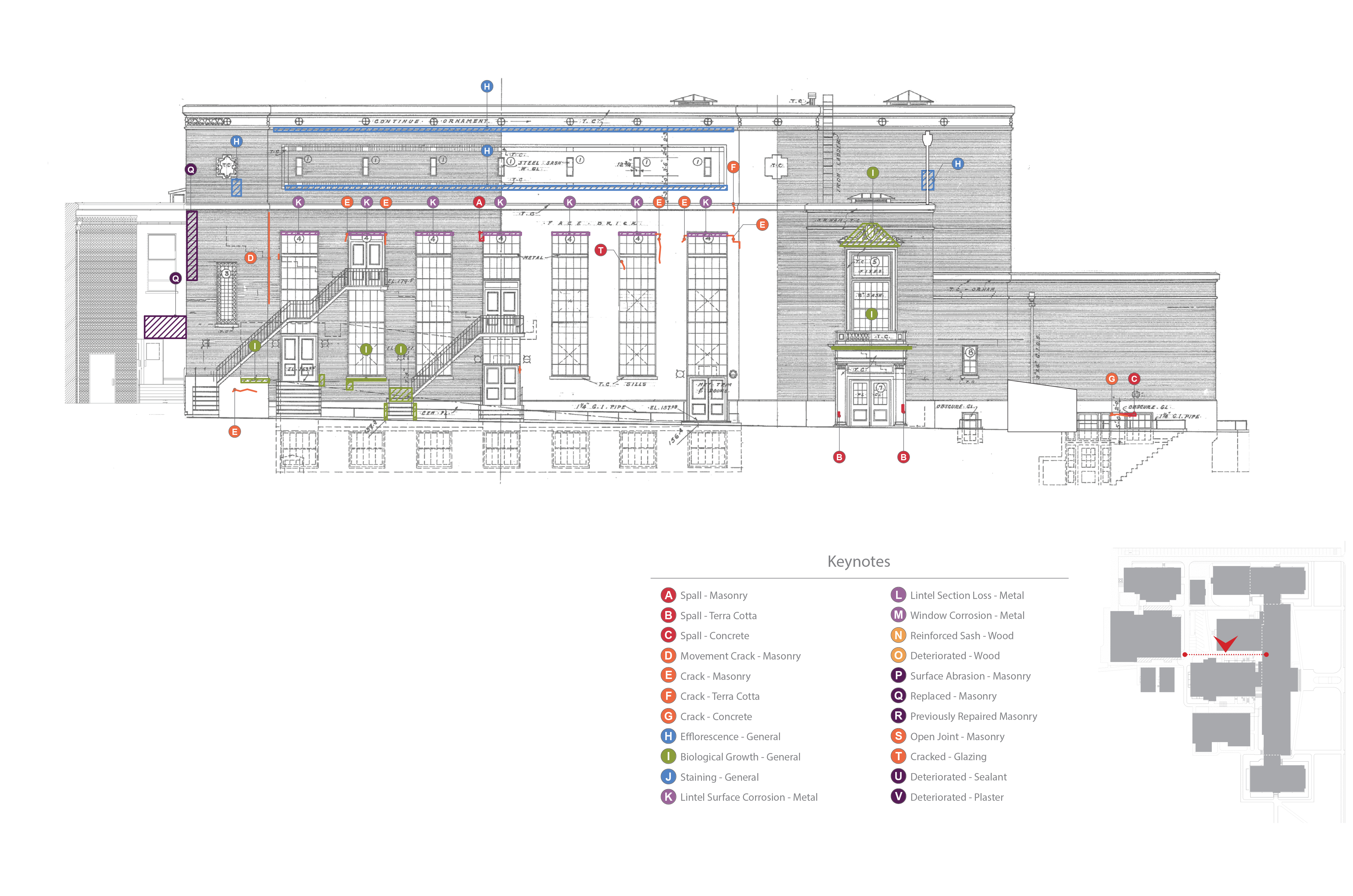
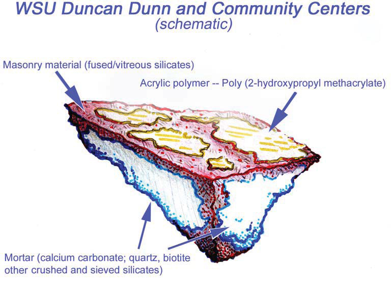
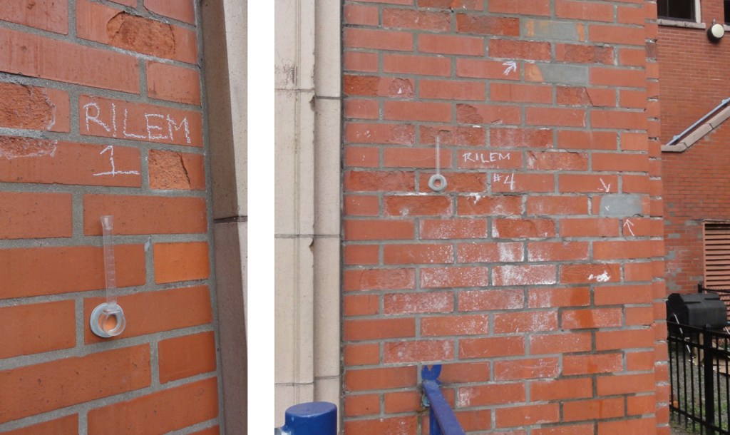
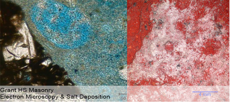
Believing the white haze was a result of UV degradation of a masonry sealer, PMA conducted Reunion Internationale des Laboratoires D’essais et de Recherches sur les Materiaux et les Constructions (RILEM) tube tests of water absorption on the exterior brick on Duncan Dunn Hall. The area of brick chosen for the test was out of direct sunlight to avoid affecting the results and was conducted during dry weather. No movement of the water over a 45 minute period was recorded during the test. Masonry units, even those constructed with high quality clays under controlled firing conditions will absorb some water. The results of the field test on Duncan Dunn, along with the white surface haze, reinforced the assumption of the presence of a masonry coating.

Communication with WSU personnel and their internal research surmised that “the building may have had a sealer put on after the original construction. [WSU cannot verify the application through original records] but do know [that a sealer] was not used on a regular basis after [construction completion.] Back in the 70’s some “miracle sealer” of some sort was introduced on Campus and used at a few locations. Duncan Dunn Hall was among the buildings [receiving masonry sealers.] Today you can see the remnants of this as a white powdery surface that almost looks like efflorescence. [WSU] does not know the name of [the sealer] product.”

To confirm the presence of the sealer, PMA conducted lab testing via polarized light microscopy (PLM) episcopic microscopy, capillary fusion and Fourier-transform infrared spectroscopy (FTIR) per ASTM D1245 and E1252, respectively. FTIR indicated the material to be Poly(2-hydroxypropyl methacrylate), an initially water-miscible acrylic polymer that in these samples is at present very brittle and sloughs rather easily.Testing confirmed the presence of a “water-miscible acrylic polymer”. Due to chemical breakdown under UV, the chalky coating remaining on Duncan Dunn is no longer soluble in water.Because of the insoluble nature of the white haze, low pressure hot-water cleaning methods would not be successful. PMA recommended the Rotec Vortex cleaning system using a mirco-abrasive mixture of dolomite, water, and air. Ultimately this removal processes was successful with no damage to the masonry surface.

(1) Patent application for new formulation of sealers. (2) Types of Masonry Water Repellents, GSA web site. Information derived from ProSoCo Inc. product literature.

Written by Peter Meijer AIA, NCARB / Principal

Analyzing Historic Masonry Wall Performance

Wilmer-Davis Hall is a residential complex on the Washington State University (WSU) Pullman campus. Built in 1937 by Architect Stanly Smith, with John Maloney, the six-story structure is composed of masonry and concrete with a masonry/brick veneer in the classical and Georgian Revival architectural styles. For a recent feasibility study of the complex, PMA provided an exterior assessment and a limited moisture study utilizing Wärme Und Feuchte Instationär (WUFI), an industry standard application in predicting wall performance to determine how additional insulation may impact the existing constructions and wall performance.

The primary concerns of this analysis included increased potential for freeze thaw action and increased mold growth as a result of added insulation. When historic buildings are insulated the insulation is typically added to the interior of the structure to prevent alterations to the exterior appearance. This often causes the outer layers of the wall to be both colder and wetter as the materials are no longer warmed and dried by the interior heating system. The additional water and more extreme temperatures can result in an increase in freeze thaw action, corrosion of metal reinforcement, and/or increased mold growth.

Additionally adding insulation to a wall changes the location of the dew point within that construction (the point at which vapor in the air condenses into water). A dew point within the middle of the wall can also result in increased moisture within the wall cavity. If a wall has difficulties drying due to any of the above causes it is possible that over the course of several years the quantity of water within the wall will consistently increase. Accumulation of water will exacerbate reinforcement corrosion and mold growth and can result in increased freeze thaw action. This study focused on the following metrics to analyze proposed wall performance: quantity of water in the assembly, quantity of water in each material layer, relative humidity in layers susceptible to mold growth, and isopleths.

MODEL SETUP
As in any simulation analysis a number of assumptions were made regarding the existing wall construction and the proposed design conditions. A variety of different conditions were analyzed in order to explore the range of conditions and variables. Below is a description of the inputs as well as an analysis of the results.

Four (4) proposed wall constructions were analyzed to determine how different types, quantities, and configurations of insulation would impact the existing constructions. The configurations were based on outlined solutions for meeting Washington State Energy Code (WSEC) or providing improved thermal comfort. Two of the proposed constructions meet WSEC (Option 1 and Option 2), while two of the solutions (Option A and Option B) fall short of fully meeting WSEC, but would provide improved insulation values. The options simulated included:

Base Case (Existing Conditions) (R-4.8)
3-1/2” Masonry
1” Air Gap
7-1/2” Hollow Clay Tile Back-Up Wall
1-1/2” Plaster

Option 1 (Meets WSEC) (R-15.4, continuous insulation)
3-1/2” Masonry
1” Air Gap
7-1/2” Hollow Clay Tile Back-Up Wall
1-1/2” Plaster
2” Expanded Polystyrene
Vapor Retarder (1perm)
0” Gypsum

Option 2 (Meets WSEC) (R-20.9, insulation is not continuous)
3-1/2” Masonry
1” Air Gap
7-1/2” Hollow Clay Tile Back-Up Wall
1-1/2” Plaster
3” Batt Insulation
0-1/2” Expanded Polystyrene
Vapor Retarder (1perm)
0-5/8” Gypsum

Option A (R 17.4, insulation is not continuous)
3-1/2” Masonry
1” Air Gap
7-1/2” Hollow Clay Tile Back-Up Wall
1-1/2 Plaster
2” Foamed-In-Place Polyurethane
Vapor Retarder (1perm)
0-5/8” Gypsum

Option B (R-18.4, insulation is not continuous)
3-1/2” Masonry
1” Air Gap
7-1/2” Hollow Clay Tile Back-Up Wall
1-1/2” Plaster
3-1/2” Batt Insulation
Vapor Retarder (1perm)
0-5/8” Gypsum

MATERIALSIt should be noted that no material testing was performed during this phase of the project – instead default material properties were chosen from the WUFI database. Materials used include:

  • Masonry: The material ‘Brick (Old)’ was used to simulate the existing masonry. The material is a generic historic brick material compiled from a variety of different bricks and included in the WUFI database.
  • Airspaces: All airspaces were modeled without additional moisture capacity which according to WUFI, models more realistic moisture storage in air cavities.
  • Hollow Clay Tile: The historic drawings indicate that behind the masonry is hollow clay tile. WUFI does not have a default material for hollow clay tile. Instead a masonry material ‘Red Matt Clay Brick’ was used to represent the solid portions of the clay tile. Air spaces were used to simulate the hollow portions of the tile.
  • Historic Plaster: The WUFI database does not have a default historic plaster material. The ‘Regular Lime Stucco’ material was used to simulate the existing plaster.
  • Batt Insulation: ‘Low Density Glass Fiber Batt Insulation’ was used in simulations.
  • Rigid Insulation/Expanded Polystrene: ‘Expanded Polystyrene’ was used in simulations.
  • Fomed-In-Place: ‘Sprayed Polyurethane Closed-Cell’ was used in simulations
  • Gypsum: ‘Interior Gypsum Board’ was used in simulations.


  • Weather/Interior Conditions In each simulation the model was set to mimic extreme situations to verify that the existing walls will perform in all conditions. The Spokane, Washington weather file indicates that the south elevation should have the most wind driven rain and moisture impacting the wall. Given this information the analysis used south exposure and the Spokane weather file to simulate exterior conditions. For the interior climate conditions the following profiles were used:

  • Interior temperatures ranging from 69 °F to 72 °F
  • Relative humidity ranging from 50% – 60%


  • The above values represent a relatively high moisture load which is consistent with the existing use as a residential facility.

    Water Intrusion Additionally as per ASHRAE 160 a small leak (1% of driving rain) was introduced into the exterior assembly to simulation a scenario where water was penetrating the exterior surface. This could occur at bondline failures in the mortar or penetrations through the wall assembly. The leak was placed past the masonry veneer on the face of the hollow clay tile backup wall.

    Initial Conditions Lastly the initial conditions of the materials were determined using ASHRAE 160. For existing wall materials EMC80 was used as the initial moisture content. (EMC80 is a value expressing an equilibrium of water and material masses at 80% humidity). For new components the expectation was that the materials would be installed from the interior and would remain dry during the construction process – thus EMC80 was used for new components as well.

    WUFI RESULTS
    Four metrics were used to interpret and analyze the following WUFI results: Total Water Content/Water Content in Material Layers, Temperature, Relative Humidity, and Isopleths.

    Total-Water-Contents-WSU-Wilmer-Davis-WUFI-Report-6
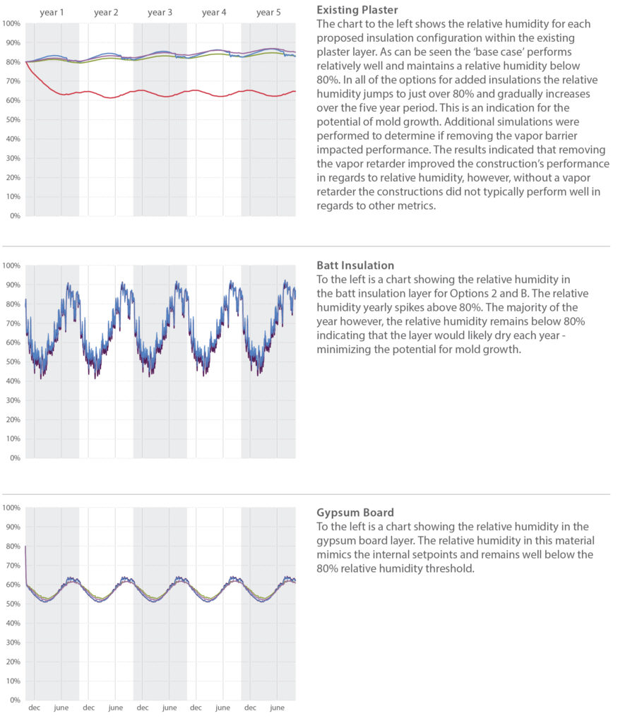
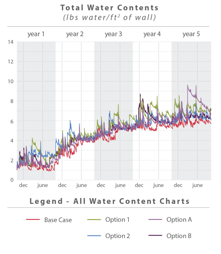
Total Water Content WUFI can predict the total accumulation of water over the time frame of the simulation, in this case five years. Over the course of each year a wall assembly will be wetted by the rain, and dry over the summer months. Differences in humidity and temperature between spaces may cause water condensation within the walls. If conditions do not allow condensation or other water to dry, materials may accumulate water over a period of time.

    The chart above shows how each of the different simulations performed. Note that total water content is measured per ft2 of wall. Walls that are thinner (existing construction) will inherently have less capacity to hold water. In general all of the walls performed in a similar manner – an indication that the retrofit strategies should perform in a comparable manner when compared to the existing walls. As can be seen in the chart, all of the simulations, including the base case showed some accumulation of water over the five year simulation. These results, however, do not conclusively show that the proposed walls will accumulate water. The results indicate that even the base case is accumulating water over time. During PMA’s site visit, however, the existing exterior walls appeared to be performing well – which would not be the case if they were consistently accumulating water. Additional analysis showed that the gradual accumulation of Total Water Content appears to be a result of initial instability within the wall construction that equalizes over time. A 20 year simulation showed accumulation over the first five years, after which the water content stabilizes.

    Water Content in Material Layers Each of the individual layers of material in a wall assembly have the capacity to hold and retain water. A high water content in any individual layer can indicate the potential for mold growth, the possibility for damage associated with freeze thaw, and a reduction in R-Value based on moisture content. Mold growth is possible when the moisture content is above 20% and if the material has the capacity to feed mold growth. The charts below show how each simulation performed for each layer within the wall.

    Water-Content-Materials-WSU-Wilmer-Davis-WUFI-Report
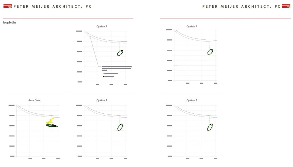
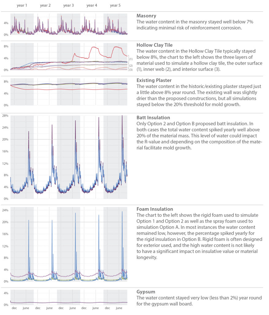
In general most layers remained well below the 20% threshold for mold growth. The insulation layers, however, are an exception. Options 2 and B both had batt and/or foam insulation which yearly exceeded 20% water. This quantity of water is somewhat concerning for the batt insulation as it may reduce the material’s R-Value and/or contribute to mold growth depending on the composition of the material. Solutions that used foam insulation performed better than those with batt insulation.

    Temperature One common result of insulating a historic building from the interior is increased freeze thaw action. Insulation prevents the interior conditioned space from heating and drying the exterior masonry. As a result the masonry is typically saturated with more water and exposed to colder temperatures. The analysis looked at the temperature within the middle of the masonry to determine how added insulation would impact the material. A chart comparing the base case to the four options for insulation is located below. As can be seen the brick temperature remains consistent with the base case in all retrofit options. This is an indication that the masonry may not by exposed to additional weathering as a result of added interior insulation. It should be noted that not all masonry reacts to water saturation and freezing conditions in the same manner. To further analyze the masonry’s susceptibility to freeze-thaw action lab analysis is recommended to determine material performance. If results indicate that the masonry is susceptible to freeze-thaw it will be critical to ensure new constructions do not lead to a significantly colder/wetter exterior wall.

    Relative Humidity The relative humidity of the air within the wall construction also has an impact on material longevity and mold potential. A high relative humidity in plaster or batt insulation layers may indicate mold growth, while a high relative humidity in layers with reinforcement may indicate the potential for corrosion. A constant and high relative humidity (above 80%) indicates the potential for mold growth. The charts to the right focus on several susceptible layers, the existing plaster, batt insulation, and gypsum board. In general the majority of the layers susceptible to mold remained below 80% relative humidity, or consistently dropped below 80% relative humidity allowing the material to periodically dry. An exception was the existing plaster layer. The addition of interior insulation caused the relative humidity within the layer to increase approximately 15%, from 65% (base case) to just over 80% (all options for added insulation). This spike in relative humidity is concerning and could indicate the potential for mold growth within the layer.
    Materials-Temperature-Relative-Humidity-WSU-Wilmer-Davis-WUFI-Report
    Isopleths WUFI can also predict mold growth by plotting isopleths on the interior surface. The isopleths are plots of the temperature and the relative humidity for every time period calculation. When the temperature and relative humidity both exceed the limiting lines calculated by WUFI there is the potential for mold growth. The simulations indicate that there is very little potential for mold growth. All of the simulations begin above the limiting lines, but over time equalize and remain well below the threshold calculated by WUFI.
    wufi-isopleths-results-wsu
    CONCLUSIONS
    The results described above indicate that there could be some challenges to designing an appropriate insulation system for Wilmer Davis Hall. Three of the primary concerns noted in the above analysis are: increasing total water content quantities; high quantities of water in the batt insulation layers; and consistently high relative humidity’s in the existing plaster layer.

    In general Option 1 and Option A performed better than Option 2 and Option B – primarily because they relied on only foam/rigid insulation. This resulted in no risk of mold growth within the insulation layers and no reduction of the R-Value. Concerns were still identified with both Options in terms of total water content and relative humidity in the plaster layer.

    Prior to detailing a new wall for construction additional analysis is recommended. Minor changes in material properties can have significant impacts on wall performance. The above analysis has indicated that there is a potential for mold growth, but has not confirmed its likelihood. Most of the metrics indicated no risk of mold growth – however because some of the metrics showed a potential for mold, additional analysis is recommended. Testing of the existing materials and specific data on proposed products should be used to refine this analysis and determine extent of mold growth risk.


    Written by Halla Hoffer,AIA, Assoc. DBIA / Associate, Architect

    When Field Performance of Masonry Does Not Correlate with Lab Results

    First presented at RCI 2015 Symposium on Building Envelope Technology, Nashville, TN

    grant-hs-alterations-over-time

    Background
    When it was completed, Grant High School was typical of the high schools constructed by Portland Public Schools in the pre-World War II era. In addition to being an extensible school, including educational buildings constructed between 1923 and 1970, the school was also reflective of fire-proof construction through its use of a reinforced concrete structure with brick in-fill. (Portland Public Schools, Historic Building Assessment, Entrix, October 2009)

    Over the last fifteen years, Portland Public Schools (PPS) noted an accelerated degree of masonry face spalling on the original 1923 main building and 1923 Old Gym particularly when adjacent to concentrated sources of surface water. Other areas of spalling were not as obvious including protected wall surfaces. The masonry spalling was not occurring on later additions including the north wing (circa 1925), south wing (circa 1927), and auditorium building (circa 1927). Upon closer visual examination, it was observed that individual units were failing in isolated protected areas of the wall surface. Failures in such areas could not be accounted for under direct correlation of heavy water intrusion and typical failure mechanisms.

    The failure of the brick was potentially due to a number of separate or cumulative conditions including 1) excessive water uptake by the brick; 2) sub-fluorescence expansion of salts in the masonry, 3) freeze thaw; 4) low quality of the original 1923 brick; and 5) the application of surface sealers preventing water migrating to the exterior surface.

    grant-hs-multi-surface-deficiencies

    Field Investigation
    In order to determine if the damage to the masonry was deeper than the surface, several wall-lets, an invasive exterior wall opening, were performed confirming the assembly of a multi-wythe masonry wall constructed in a typical fully bedded bond course with interlocking headers and no cavities between the first three brick courses. Hooked shaped, 3/32” gage, steel wire masonry ties in alternating courses and approximately twelve inches (12”) on center ties were found to be in good condition with no deterioration. The absence of corrosion on the in place brick wire ties indicated that little moisture was present inside the multi-wythe wall.

    As a result of the hypothesis and field observations, it was prudent to conduct a series of lab tests to the brick, mortar, and patch materials to assist in the determination of 1) the quality of the brick; 2) the physical composition of the brick; 3) the quantity of naturally occurring compounds in the masonry and mortar, particularly salts in the masonry; and 4) the quality of the mortar. The findings would help narrow the potential cause of the spalling and lead to a more focused repair and maintenance process. Bricks were removed for testing of Initial Rate of Absorption (IRA – a test for susceptibility to water saturation) freeze thaw testing, and petrographic analysis, a way to determine the inherent properties of the clay and manufacturing process. Both pointing and bedding mortar samples, as well as, the previous patching material were removed and also tested. To rule out damage caused by maintenance procedures, faces of the brick material were sent to determine if sealants were used on the brick and, if present, determine the sealant chemical makeup. The presence of a surface coating may lead to retention of water within the brick and thus prevent natural capillary flow, natural drying, and water evaporation.

    grant-hs-field-testing

    Testing & Results
    Samples sent to the lab for coating assessment were analyzed via episcopic light microscopy, and Fourier- Transform Infrared Spectroscopy (FTIR) per ASTM D1245 and ASTM E1252. The results found no hydrocarbon or organic formulations used on the surface of the brick refuting the hypothesis of a surface sealer.

    Following modified ASTM standards, a 24-hr immersion and 5-hr boil absorption test on the brick were performed. The brick have a very low percent of total absorption at 9.5% for the 5-hr boil and 7.5% for the 24-hr test. The maximum saturation coefficient is 0.79 which is 0.01 over the maximum requirements for Severe Weathering bricks recommended for Portland climate (ASTM C216-07a Table 1). The Initial Rate of Absorption (IRA) is 5.7g/min/30in2 which equates to a very low suction brick or brick with low initial rates of absorption. The freeze thaw durability tests resulted in passing performance. All of these tests refuted the hypothesis that freezing temperatures were the cause of masonry spalling.

    A brick material analysis was performed in general conformance with ASTM C856, ASTM C1324 (masonry mortar) and included petrographic analysis, chemical analyses, x-ray diffraction and thermogravimetric analysis. Samples were analyzed under a polarized light microscope for information such as materials ratio and presence or absence of different deterioration mechanisms. These tests were used to assess the overall quality of material, presence of inherent salts, excessive retempering, cracking, ettringite formation, and potential alkali‐silica reactivity.

    grant-hs-electron-microscopy-salt-deposition

    The Petrographic Characterization resulted in the most unusual findings and the most relevant results related to the observed failures. The polarized light microscope indicated carbonate based salt crystals seeping into the masonry from the mortar. No sulfate based salts, typically associated with the clays used for making brick, were present. Furthermore the inherent properties of the brick showed very small rounded voids and interconnected planer voids. Planner voids result from poor compaction during the raw clay extrusion process prior to firing.

    Performance of brick in the field is a result of both material properties and resistance to micro-climates within the brick’s capillary void structure which cannot be repeated in the lab. Studies have shown a connection between small voids in the material property and susceptibility to longer water retention near the surface. With natural absorption properties, the brick is taking in a small quantity of water in very small pores. 24-hour immersion results are very low (7.5%). Publication of more in-depth studies correlates maximum saturation values for brick with low 24-hour immersion values. The effect of low immersion values and small quantities of absorbed water may increase the susceptibility in brick with small pore structure to freeze thaw failure.

    The presence of salt migration out of the mortar and into the brick, plus small pore structure and low immersion values, combining with a cleavage plane resulting from manufacturing are contributing to the Grant High School brick spalls. Brick with smaller pores are less capable of absorbing the expansive forces of freezing water and drying salts. Interlaced pores creating linear plains parallel with the face of the brick create stress failure points resulting in surface spalling. Since the characteristics of the brick resulted from the firing and manufacturing process, the brick will remain susceptible to the failure mechanisms.

    Conclusion
    Field observations of masonry failures generally correspond with known failure mechanisms. However, it is not unusual that further analysis is necessary to confirm in-field performance and that typical laboratory test results are in conflict with in-situ performance.

    The best corrective action is to minimize the amount of surface water and proper mortar joints and mortar composition. Additional spalls are likely to occur in the future due to the accumulation of expansive forces over a long period of time. Replacement of the spalled bricks is recommended over further patching. Leaving spalled brick in place will continue to worsen the condition over time and affect adjacent brick.

    grant-hs-present-day


    Written by Peter Meijer, AIA, NCARB, Principal

    Assessing Union Station to be Part of Our Future

    Portland’s Union Station is the only major railroad station built in Oregon, and one of the oldest major extant passenger terminals on the West Coast. From its inception, Union Station has functioned as a major transportation link to Portland and the west coast, with a continued vital role to play in future rail and multimodal transportation planning.
    Union-Station-Historic-photo
    A Sense of Place
    Critical to adapting Union Station, and other historic structures, for current and future use is to thoroughly understand key elements and components that convey the sense of place and rich history of the structure. A deeper understanding enables informed decisions to be made about the potential of key characteristics to remain for future generations. Union Station was constructed between 1892 and 1894 and was designed by Van Brunt & Howe architects in the Queen Anne style with Romanesque detail. From 1927 thru 1930, the Main Concourse was modernized by Portland’s internationally known architect, Pietro Belluschi, to reflect the streamline era of rail technology. Like the original 1892 elements, the Belluschi modernization’s are equally important stories to tell.

    Creating a graphic document annotating “changes over time” is an essential tool for evaluating how Union Station has adapted to improvements in rail technology, fluctuations in passenger volume, cultural shifts regarding train travel, as well as modifications to specific architectural elements that impact the historic integrity and interpretation of original design intent.
    Union-Station-Report-Outline-pg2
    Methodology for Assessment
    Our method of developing the graphic drawing is to compare historic floor plans and historic photographs to current plans and images through a process of layering plans from different eras over one another and drawing the altered, or missing, elements (e.g. walls, furniture, spaces, etc.) in different colors. This methodology provides an easily interpreted floor plan. The use of color enhances the image and creates a visual record of both changes and original historic fabric. In reading the graphic drawing, it becomes readily discernible that changes include: wood floors replaced with concrete and new floors added; openings in the main concourse were moved and enlarged; the women’s waiting room and toilet were removed to widen the south hall, the stairs were renovated, and a new baggage counter was constructed. The covered concourse was glassed in and a section was made into the First Class Lounge, which remains today. And in the 1940s, a nursery, or crying, room was added.
    Union-Station-PMAPDX-drawing
    What is fascinating about the history of a building like Union Station, is that the rail lines and street patterns are also integrated with the function and use of the structure and have changed over time as well. The construction of Union Station came soon after Portland was fully connected by rail in 1883 to California, Montana, and rail lines running to the East Coast across the U.S. The Spokane-Portland-Seattle rail connection was finished in 1908. In 1922, Union Station became accessible to all major passenger railroads operating through Portland.

    When originally constructed, six passenger car rail lines approached the rear of Union Station. The waiting platform consisted of planks on dirt with no canopy. The block across from Union Station consisted of a small restaurant, bar, other stores, and stables. A five foot iron fence bordered a large lawn and sidewalk to the south and west of the station. The High Shed, a large two-story metal shed was the first canopy built to cover the passenger platforms and extended perpendicular to the station. Under this High Shed, two smaller scale platform canopies were erected paralleling the tracks. A mail canopy was built at the north end of the building in 1915.

    By 1920, the block across from Union Station’s main entrance had been converted to parking to relieve congestion. As automobile use increased throughout the city, parking configurations were constantly changing over the years. By 1923, an elevated walkway was built to connect the Broadway Bridge to the main entrance.
    union-station-pmapdx-changes-overtime

    With the introduction of larger diesel locomotives and potential for high speed rail along the northwest corridor, the track, platforms, and canopies have had to be modified. Safety and accessibility have also driven the need for changes and modernization. Documenting these alterations with graphics, provides a foundation from which to advocate for further refinement while recognizing historic precedent and protection of historic elements.

    union-station-pmapdx-historic-photo

    Written by Peter Meijer, AIA,NCARB, Principal

    PMA is part of the DOWA-IBI Group team for this exciting PDC Union Station Renovation Project.