Tag Archives: blog

Washington Park Reservoirs

With the Portland City Council’s final decision not to further delay projects to build new reservoirs to replace the five historic open reservoirs, on the west side of the city in Washington Park a new below grade water storage tank is being planned in the general footprint of one reservoir. The second of the two reservoirs at Washington Park will be decommissioned and used for new purposes. The implementation of underground storage tanks may still elicit a spirited discussion. And at the heart of the discussion is how to implement thoughtful change to a historic, well loved cultural resource to the rigors of rapidly evolving public safety and seismic protection mandates.
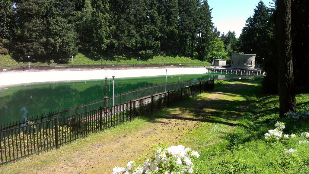
WA Park Reservoirs
Reservoirs 3 and 4
Reservoirs 3 and 4 were constructed as part of the Bull Run water system, a gravity-fed mountain watershed system built between 1894 and 1911 to provide the City of Portland with high quality drinking water. Reservoirs 3 and 4 continue to function as the city’s primary water distribution source for the west side of Portland. The reservoirs have been in continuous operation for more than 100 years. They serve as a featured amenity enriching the landscape of Washington Park, one of Portland’s largest and oldest parks, with vistas of open water, and period historic structures. Also due to their location on hills on the west side of the city, scenic views are afforded across the reservoir water.

As summarized in the National Register of Historic Places nomination, “one of the most defining landscape principle of Reservoirs 3 and 4 is the open expanse of water, their irregular shape, rusticated concrete structures, and ornate wrought iron detailing of fences and lampposts. The reservoirs are a striking and elegant addition to the serene forest that makes up this end of Washington Park. The surrounding forest is composed primarily of Douglas fir, western red cedar, and big leaf maple all predominating native tree species of the Pacific Northwest.”
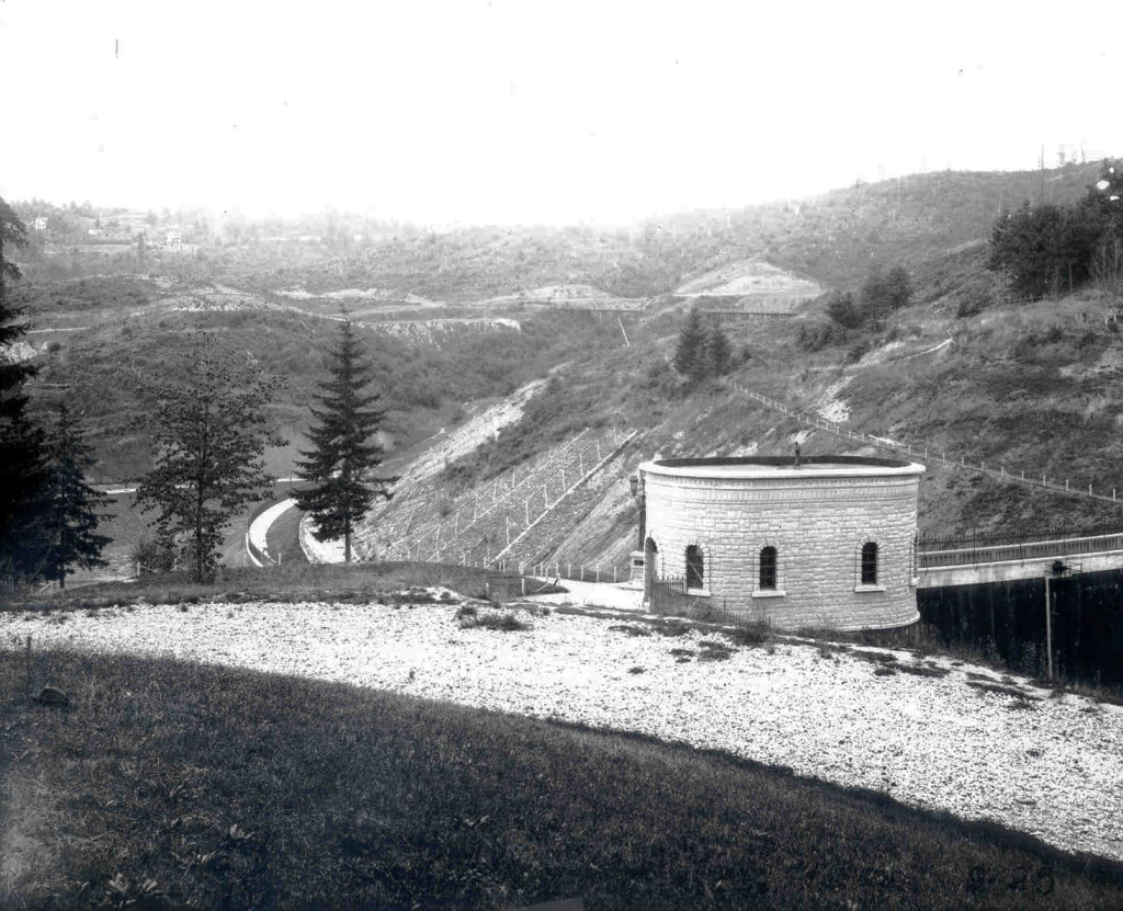
Historic 1894 photo of WA Park Reservoir 3
The Design Challenge
The challenge is to design a 100 year plus engineering solution while simultaneously designing a thoughtful change to the context, natural park setting, and historic district. Arising from the Olmsted Brothers vision for Portland and the City Beautiful movement, the changes to the Reservoirs offer an opportunity to evaluate the evolution of development outside Washington Park within the Park, changes to the Reservoirs themselves, public access, and protection of cultural amenities. If access to the “water” is transformed to a public amenity, how does the design enhance the serene qualities of the site? How should the change reconnect the reservoir area with the surrounding neighborhood and Park features?
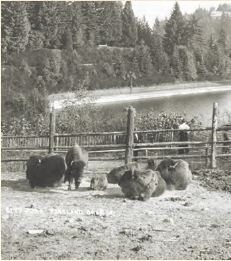
WA Park ZOO circa 1900The reservoirs embody the challenge associated with retaining a historic place as both a visual element and a dynamic landscape. The safety, security and seismic solutions may alter the purpose of the visual feature and the interaction with the “water,” but that does not translate into a diminishing of a historic place. There are no easy answers. In the end, this final decision should be assuring that the Washington Park Reservoirs will continue to provide safe, reliable water storage, and to elicit wonder well beyond the next 100 years.


Written by Kristen Minor, Preservation Planner

Preserving an Icon

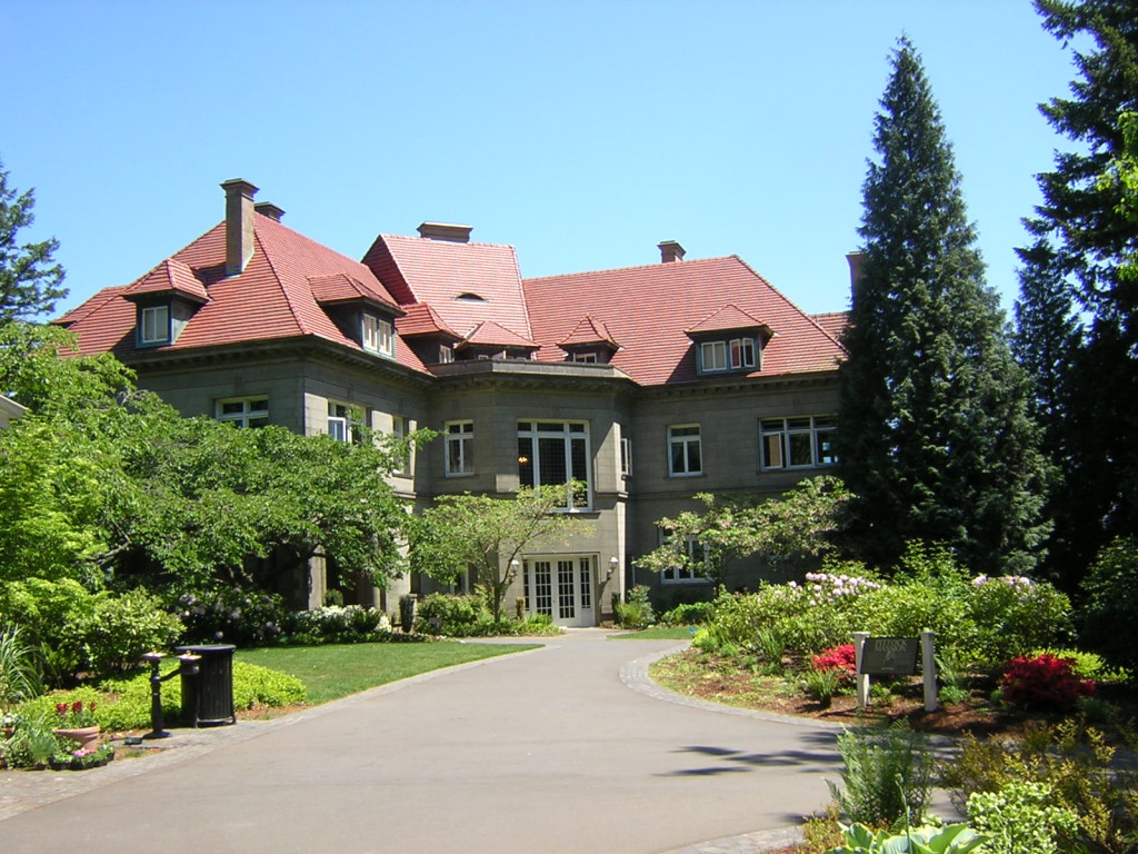
Under the leadership of the Pittock Mansion Society, Portland Parks & Recreation, and hundreds of volunteers, the venerable Pittock Mansion is undergoing the first phase of preservation activities in anticipation of the Mansion’s Centennial celebration. Built for Henry Pittock, an Oregon pioneer, newspaper editor, publisher, and wood and paper magnate, “the Pittock Mansion occupies a place of special importance for Portland. It is a City of Portland Historic Landmark, a State of Oregon Landmark, and a national landmark listed in the National Register of Historic Places. The City of Portland owns many historic landmark properties, but Pittock Mansion is the only [property] operated as a historic museum [within] the city parks system.” (Historic Structures Report, 1st Edition, A Staehli, 1984)
Pittock Mansion Site Observations
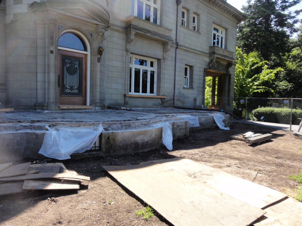
After successfully raising funds, and with City Council approval of additional funding, the Pittock Mansion is repairing the exterior terraces with new waterproofing membranes, new sandstone replacing inappropriate concrete castings, and structurally reinforcing the baluster railings so that all the brides and grooms, admirers, and visitors, can once again perch and pose with the vista of Portland and Mt. Hood as the splendor of Pittock Mansion is in front of them.

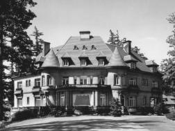
“Pittock Mansion was design in 1909 by Edward T. Foulkes and took five years to complete. Georgiana Pittock, wife of Henry, died in 1918, having lived in the house for only four years. Despite its prominent site, imposing French Renaissances exterior, formal rooms and parlors, and impressive central hall with a grand stairway, Pittock Mansion was fundamentally a home for a family with modest tastes having lived most of their lives in undistinguished Victorian houses in downtown Portland.” (Historic Structures Report, 1st Edition, A Staehli, 1984)
Pittock Mansion Terrace Repair PMAPDX
Original stone quarries are no longer operational, so an exhaustive search for replacement stone was conducted finalizing in a selection of stone from Idaho closely matching color and texture of the original. Local and regional craftsman are again involved in the careful dismantling, numbering, cleaning, fabrication, and re-installation of the stone details. New terrace tile, selected to better match the variegated colored clay tile roof, will be installed with a new waterproof membrane and improved flashing details. The original glass “sidewalk” purple lights that admit light into the basement will remain for all to enjoy.

Histoirc photo Pittock MansionThere is still much work to be done. The Pittock Mansion Society has identified the top priority projects ranging from the practical structural and electrical work to additional programming and preservation projects. The Centennial celebration will be a grand formal affair, fitting for such a magnificent and unique cultural icon within the City of Portland’s stewardship.


Written by, Peter Meijer AIA,NCARB, Principal

Preserving the Modern in St. Louis

St. Louis, MO is home to several architectural gems from the mid-century modern era. The city recently conducted a property survey of over 2,000 non-residential buildings constructed between 1945 and 1970. The Cultural Resource Office of St. Louis is highlighting a selective survey & inventory of 200 significant properties with input from PMA and the public to help develope a master list of 25 of the most significant mid-century modern masterpieces. Surveying these architecturally significant structures gives a voice to a past era that still directly influences today. St. Louis’s built heritage from the mid-century modern era showcases structures from internationally recognized architects that revolutionized architecture and design throughout the 20th century.

A Legacy of Modern Architectural Design
The post-World War II era in the United States led to the development of the Modern Movement Architecture across urban areas. Contributing factors of this development included the impact of the auto industry on the built environment, a more cost-conscious public and government, and several technological advances. In addition to these factors, St. Louis was home to the prestigious school of architecture at Washington University. The school had diverse and international students and teachers that contributed to some of the most prolific designs of modern architecture.

When discussing St. Louis mid-century modern architectural design three architects stand out: W.A. Sarmiento, Gyo Obata, and Minoru Yamasaki. Their designs were sleek, yet whimsical, and made St. Louis globally recognized for its modern architectural designs.

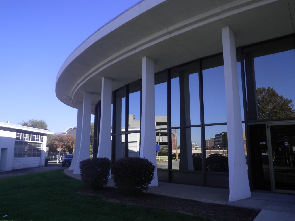
W.A. Sarmiento design

W.A. Sarmiento design

W.A. Sarmiento is an internationally regarded architect who designed some of the most prolific buildings in the city of St. Louis. A native of Peru, Sarmiento began as a draftsman for Oscar Niemeyer. In 1952 he accepted a position with the Bank Building & Equipment Corporation. From 1952 through 1964, Sarmiento revolutionized the design and function of banking facilities. Ten years after working for the Bank Building & Equipment Corporation, Sarmiento left after J.B. Gander’s death and formed his own company. W.A. Sarmiento Architects expanded to included offices in St. Louis, Phoenix, and San Francisco. Sarmiento closed his practice in 1978 and left behind a legacy of modern architectural design including the saved American Automobile Association (AAA) Building (1976), the Chancery of the Archdiocese of St. Louis (1962), and the Jefferson Bank and Trust Building (1955).

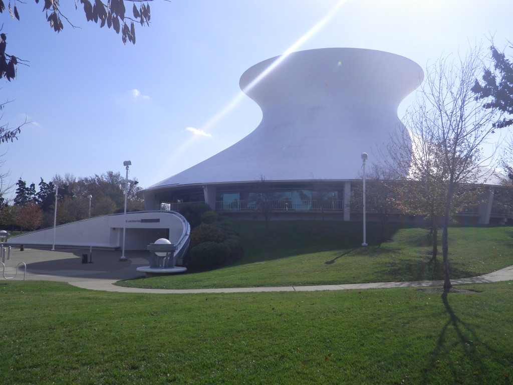
St. Louis Science Center James S. McDonnell Planetarium (1963

St. Louis Science Center James S. McDonnell Planetarium (1963


The St. Louis Science Center James S. McDonnell Planetarium (1963), was designed by the local firm of Hellmuth, Obata, & Kassabaum (HOK), with Obata as lead designer. HOK was founded in 1955, and to this day is a global leader in architectural design. The practice began by designing schools in suburbs of St. Louis, and by the 1960s it a grown and began to open offices nationally, with their first international branch opening in 1984. Obata was the lead designer of the Saint Louis Science Center along with other notable St. Louis buildings. The building has a visually striking and expressive shape, somewhat reminiscent of a nuclear power plant tower. It is a thin concrete shell structure, hyperboloid in section. This architectural design is a premiere example of continuous contemporary design.
Lambert International Airport

Lambert International Airport


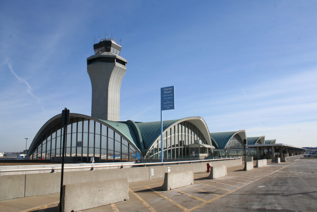
Minoru Yamasaki’s domed design for Lambert’s main terminal became the forerunner of modern terminal building plans. In 1951, the firm of Hellmuth, Yamasaki, and Leinweber was commissioned to design and update the Lambert- St. Louis Municipal Airport. In 1956, their design was the first building in St. Louis to receive a National AIA Honor award. This building was originally composed of three vaults, with a forth added in 1965. Yamasaki’s design became a model for a new generation of airport terminals. Eero Saarinen’s designs for the TWA terminal at John F. Kennedy Airport in New York, and the Dulles Washington Airport terminal both echo the repetitive concrete vaults of Lambert St. Louis Municipal Airport.

STL MODERN logo PMAPDXFor more information about this exciting project, including a list of buildings for intensive research, mid-century modern properties, city map with property locations, and property descriptions. Visit: Mid-Century Modern Survey


Written by Kate Kearney, Marketing Coordinator

Horizontal Ground Motion: A Call for More Seismic Research

There is a lack of significant research and seismic performance studies on the resiliency and inherent strength redundancy of older buildings.

U.S. Post Office & Courthouse, 7th & Mission Streets, SF

U.S. Post Office & Courthouse, 7th &; Mission Streets, SF

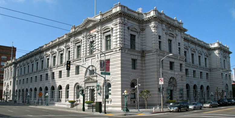
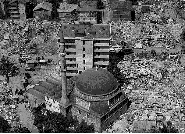
In specific, the capacity of existing buildings to resist ground motion associated with earthquakes has not been fully developed or thoroughly researched. Based on damage from earthquakes, especially the 2010 Canterbury and 2011 Christchurch earthquakes in New Zealand, with additional seismic activity lasting nearly one year, the general thought is that older existing buildings perform poorly in response to ground motion. When analyzed further, the damage from the Christchurch earthquake was predominantly due to acceleration in a vertical direction, literally tossing buildings in to the air. The peak vertical acceleration during the Christchurch earthquake exceeded the design criteria for today’s modern buildings. Not lessening the severity of the event, nor proposing for less stringent seismic codes, the Christchurch earthquake would flatten most modern cities regardless of building age. Adequate resistance to vertical movement cannot be achieved with current engineering techniques and therefore research and performance studies regarding the resiliency of existing structures must concentrate on horizontal ground motion.

1906 earthquake, Montgomery Street block, SF

1906 earthquake, Montgomery Street block, SF

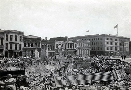
Because little can be done to prevent building collapse during vertical motion, seismic strengthening techniques focusing on dampening and resisting horizontal motion are applicable to existing structures as well as new structures. However, there has not been significant studies documenting and establishing the inherent strength to resist horizontal motion due to redundancy and mass of archaic construction methodologies. Independent performance evaluations of unique structures have occurred in the United State, Italy, Mexico, the Baltic, and others regions around the world without formal comparative analysis of the results or thorough in-depth dissemination and publication of the studies. For instance, in Oregon, informal static shear testing of a circa 1925 public middle school’s interior fire block and plaster wall surprised structural engineers when the walls did not crack at the shear planes (i.e. floor and ceiling connections) and strength measurements exceeded code allowance fivefold. (2001 Portland Public Schools shear test) When calculated and tested, the ½ inch chalk boards added even more in-plane horizontal resistive strength. The result of the testing saved the school district approximately $ 1 million in seismic upgrade costs. There was no formal documentation of the result and there has been no known similar testing performed on other existing school properties.
mosque
The seismic resistance of existing structures is affected by the structural typology, the construction materials, the varying modifications, and deterioration and decay of materials over time resulting in unique conditions that are not readily transferrable to other structures. However, sporadic investigation and research performed on existing structures and published by the international RILEM Technical Committee 20 TBS in the article “Specific recommendations for the in situ load testing of dwellings and of public and industrial building structures,” and published accounts of independent studies in journals such as the Association of Preservation Technology Bulletin offer insight into the potential redundant strength capacity of existing structures to resist horizontal ground motion.

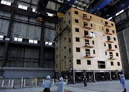
full scale shake tableThese studies combined with documented field assessments and field evidence of older structures surviving earthquakes and repeated ground motion disturbances over several hundred years are available in numerous communities and offer case study structures for further research. The numbers of university engineering departments with “shake tables” (e.g. Portland State University) create opportunities for joint partnership with private sector consultants, public agencies, and professional organizations to assess and analyze the unique aspects of archaic building materials and methodologies for seismic response. The collaboration between university and private cooperation for seismic research has the potential to develop a wealth of practical and applicable information. The current collaborative efforts involving energy consumption offer the model from which to base seismic research.

A development of systematic research, publication, and dissemination of the inherent strength of existing structures to resist horizontal ground motion would benefit all communities across the globe.


Written by Peter Meijer AIA, NCARB, Principal

Historic Preservation and New Construction in Historic Districts

Historic Districts are not frozen in time.
Ideally, Districts are busy, vital places where people live, work, socialize, and see community values reflected. Typically, buildings contribute to a district and share common characteristics becoming more historically valuable as a group than as individual properties. If we create, restore, and invest in Historic Districts, the Districts will continue to tell a story about a particular time period, a particular community, or perhaps a particular industry. So is new construction appropriate within a Historic District, and if so, how does one properly design and integrate the new building within the existing historic context? This posting will explore some factors and opinions on new construction in Historic Districts.
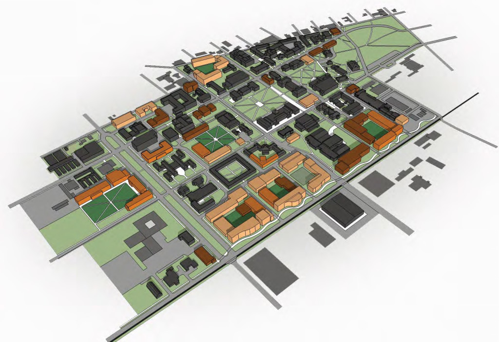
PMAPDX OSU Buildable Landarea
Some individuals argue that appropriate infill must be visually identical to nearby historic resources. Most architects in practice today have a condescending reaction against recreating previous styles as making “faux” or “Disneyland” architecture, even though western architecture for hundreds of years has recycled various stylistic revivals. It is not an absurd concept to design and build beautiful, high-quality buildings that reflect an older style and method of construction. Other individuals have no trouble placing a contemporary structure next to older structures, since modern buildings have a responsibility to reflect our shared culture and lifestyle.

Neither of these absolutes works for most situations. New buildings, as stated in the Secretary of the Interior Standards, do need to be “differentiated” from contributing buildings in a District to avoid a false sense of history. The question is how much differentiation is required? Though there are cases where a “missing tooth” in a very cohesive pattern of buildings should be constructed to resemble its historic neighbors, in other cases the visual diversity of architectural styles and periods within a District allows for more flexibility in differentiating new buildings. Historic Districts are listed on the National Register because they possess a concentration of buildings that are linked either historically, aesthetically, or both. One Historic District might represent a fairly large span of time, various architectural types and styles, and a number of different uses. Another District might be much more specific in its focus.

Opsis Architecture for OSU

Opsis Architecture for OSU


As Preservationists and Architects, we need to analyze the characteristics and contexts that are the same and the characteristics and contexts that are different about the resources within the District. Each case is unique and site-dependent. It is possible to allow for stylistic additions and change without showcasing the change; to temper the inclination to design an individually iconic building; and to limit a modern “intrusion” so as to respect and highlight the older buildings. Good design, high-quality detailing, and high quality materials contribute towards compatibility, and adaptive reuse and change is inevitable to the vitality of a Historic District.

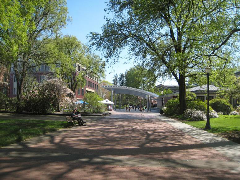
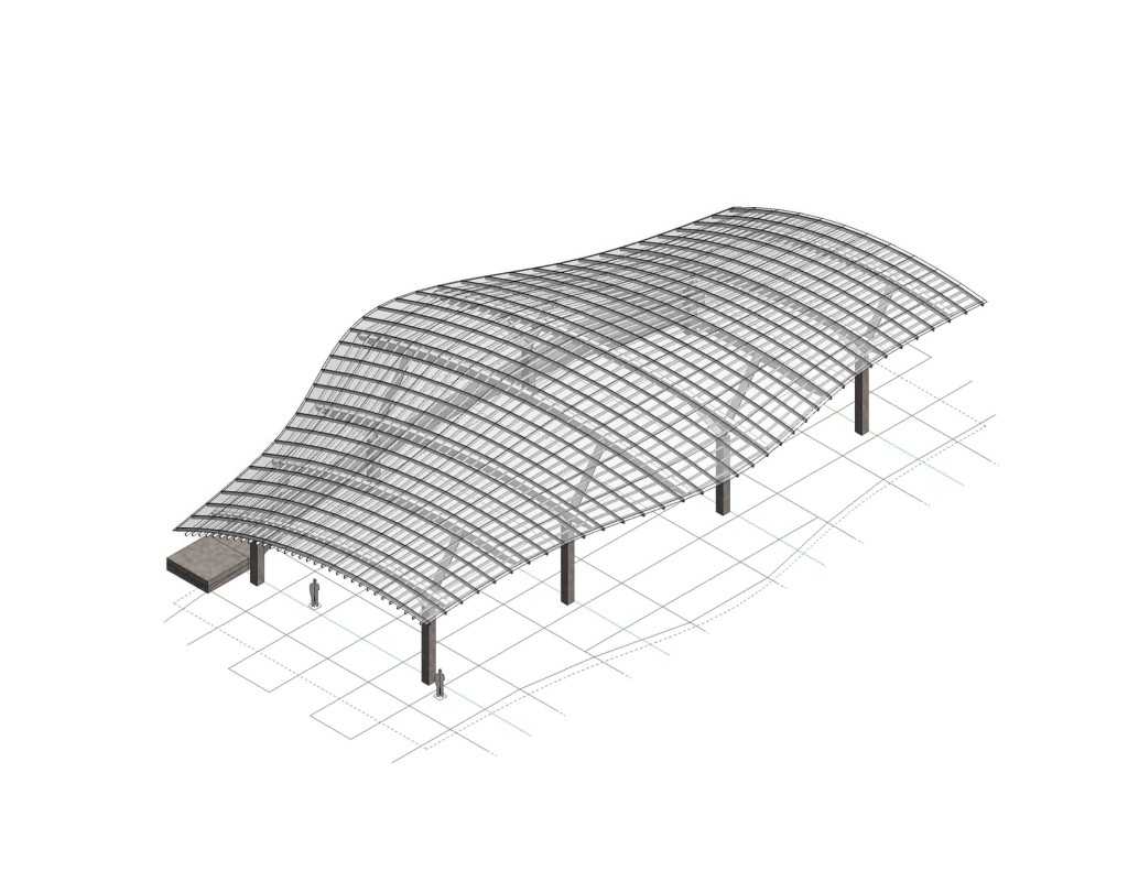
Each jurisdiction having authority makes its own interpretation of what it means to be compatible. One recent example is an approval by the Historic Resources Commission (HRC) in Corvallis, Oregon. The Corvallis HRC approved a design for a freestanding metal and glass canopy in the heart of the national registered Oregon State University Historic District. The HRC concluded that there was no historic precedent for a freestanding non-building element, but found that the canopy was visually light and well-designed and fit into the open space pattern of development without detracting from the neighboring Contributing resources. The role of the historic consultant in this case was to construct an argument as to why the canopy was compatible in the District, and push back against earlier suggestions that the canopy become more “building-like” with masonry columns. An open structure with a veneer of building material would have created a less compatible design.

Opsis Architecture Canopy design for OSU

Opsis Architecture Canopy design for OSU


Each proposal for new construction in a Historic District should be informed by its context. There is latitude for new construction to be distinct, as long as the new work does not detract from the surrounding historic resources.


Written by Kristen Minor, Preservation Planner
Burnt Clay Facades

Terra cotta, or “burnt clay,” is a hard baked, high grade of weathered or aged clay. It is similar to brick but the clay is of higher quality and fired at higher temperatures. This article focuses on exterior architectural terra cotta as distinguished from statuary, pottery , and terra cotta blocks used as inner wythes of wall or fill material.
300px-Court_of_Honor_and_Grand_Basin
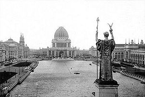
The 1893 Columbian Exposition in Chicago demonstrated the versatility and ornamental qualities of terra cotta. It highlighted the great variance in color and shapes possible with terra cotta and began the demand in the United States for terra cotta that lasted through the late 1930s. Terra cotta is prized for its light weight, longevity, aesthetic qualities, and unit construction. At the peak of production, almost every urban area in America was producing architectural terra cotta in some variation. Today, most replacement units are produced by either Gladding McBean or Boston Valley Terra Cotta.

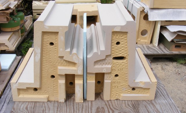
Specific forming techniques including hand press, machine press, slip casting, and extrusion are used depending on the shape and style of unit required. In the analysis of terra cotta failure the forming techniques are less critical than the strength characteristics of the fired clay, the integrity of the exterior surfaces, and structural support systems.
Boston Valley new TC
Exterior ornamental terra cotta was marketed as a light weight water proof cladding. And if proper construction techniques were employed, and the system was maintained, and the local climates were mild, terra cotta performed as sold. However, terra cotta adorns buildings in severe weather climates, and is installed with structural materials affected by environmental conditions, and located on façade elements inaccessible for routine maintenance.

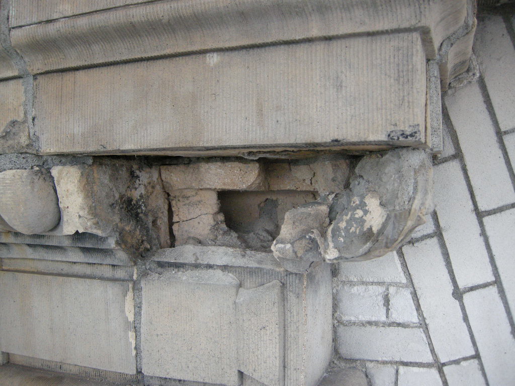
The mortar joints are the material most susceptible to failure. Joints often exist on all three axis with some units of terra cotta designed for flat horizontal surfaces. Over time and exposure, the mortar fails providing a means for water intrusion. Sever cycling of weather in simultaneous freeze/thaw conditions can cause the terra cotta clay to expand and contract, accelerating the crazing or cracking of the protective glaze. Extensive crazing can lead to glaze spalling and allow for further water intrusion.

Once water enters the system there is no weep path allowing for water egress. Construction means and methods, as well as the cellular unit design, trap water and contribute to the potential corrosion of steel lintels, wire ties, steel structural support members, and other miscellaneous metals. Rapid freezing and thawing cycles, in addition to steel corrosion, can crack terra cotta units. If the units remain unrepaired, further water intrusion and/or absorption will occur.
121022 QAHS S Elev 094
The repair of terra cotta will depend both on the cause and manifestation of the defect. Typical defects include crazing of the glazed finish, shallow surface spalls, deep spalls affecting the bisque, cracked units, inadequate support and / or anchorage, corrosion induced stress fractures, impact damage, mortar degradation, lack of maintenance, and inadequate repairs.

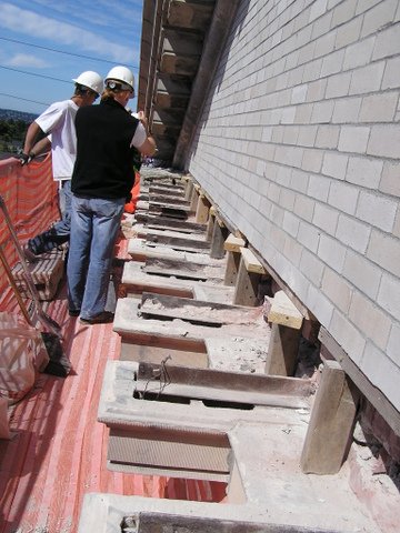
Proper terra cotta repair methods are linked to the cause of defect. Repair techniques are often performed on-site by skilled tradesmen. When damage to the terra cotta unit is severe, full replacement may be required. Defects due to inadequate support or a result of corrosion to supporting steel members is likely to require more invasive repair strategies including removal and replacement of several courses of interlocked terra cotta units.

QAHSCWhen replacement units are not required and the scope is limited to on-site repair, labor costs exceed material costs. Since many historic terra cotta units were specialty designed and installed for the structure, a premium price is paid for replacement. New exterior decorative terra cotta is available only from the sources referenced and with small quantity orders, the first unit is approximately $5,000 with much of the costs attributed to making the form and determining the finish color and texture. Subsequent costs per unit will decrease with the range of decrease dependent upon quantities required.
The most important component of terra cotta repair is an understanding the cause of deterioration and the proper repair specifications. Both are derived after a full condition assessment and evaluation of the existing conditions.


Written by Peter Meijer AIA, NCARB, Principal


——————–
Sources
• Last of the Handmade Buildings, Virginia Guest Ferriday, Mark Publishing Co., Portland, OR 1984
• National Park Service, Preservation Brief No7, Preservation of Glazed Terra Cotta
• APT Pacific NW Chapter 2005 workshop
• Terra Cotta, Standard Construction, Revised Ed., National Terra Cotta Society, 1927

The Challenges of Assessing Structural Brick Veneer Panels

The origin of Structural Brick Veneer Panel dates back to the early sixties when new “tensile strength intensive” exotic mortar combined with steel reinforcing to create a 4-inch thick, single wythe brick panel. Developments continued to occur throughout the 1960s and 1970s, peaking in use during the 1980s. The system was relatively expensive due to the use of the high tensile strength mortar.
Koin Center brick pane
Developments in both the high tensile strength mortar and the clay units continued to reduce cost and allow the use of regular reinforcing and standard mortar and grout. Newer systems and manufacturing processes accommodated both horizontal and vertical reinforcing and permitted high-lift grouting. Later advancements in the connections of the brick veneer panel system to the building frame resulted in the use of brick veneer panels system on multi-story high-rise office buildings, schools, apartment buildings, residences and many other applications throughout the United States and the Pacific Northwest.
cracked brick_design guide
Major Failure Mechanisms
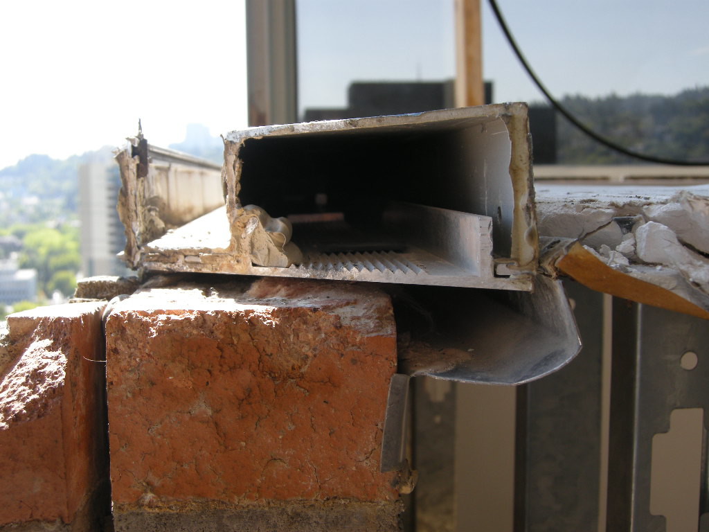
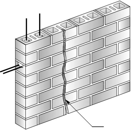
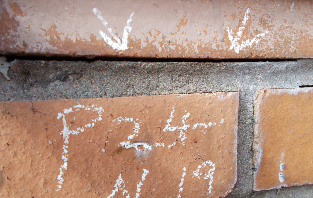
There are two major failure mechanisms of Structural Brick Veneer Panels: water intrusion and mortar/grout additives. Water intrusion can occur from a lack of adequate flashing at the window head and sill interface, carbonization of the mortar, and structural cracking. Brick veneer panels are commonly designed to allow for limited cracking at the horizontal bed joints at the brick to mortar interface. Masonry veneer panels leak more through the mortar and brick interface than through the masonry unit itself. If the mortar and brick interface is cracked, as is permitted under structural design calculations, water infiltration will increase. A cement based material, panel mortar will carbonize over time decreasing the protective alkalinity environment surrounding the reinforcing bar and thus increasing the potential for corrosion. The largest volume of water intrusion is typically associated with inadequate window systems that fail to keep water out of both the structural brick veneer panel and the cavity interface.
024
The durability of the wall is highly influenced by the quality of the mortar joints and interior cell grout. The specification should require reconsolidation of the grout or the incorporation of additives that balance expanding, retarding, and water reducing agents to provide a slow, controlled expansion prior to the grout hardening. Mortar/grout additives, particularly those developed in the 1970s, containing vinylidene chloride can initiate and accelerate reinforcing steel corrosion under the right conditions. The composition of the mortar/grout is determined through laboratory analysis of chloride content, vinylidene chloride, and pH level.

Repairs to structural brick veneer panels is labor intensive and may involve panel replacement, panel encapsulation, window system replacement, and/or extensive individual masonry unit repair.


Written by Peter Meijer AIA,NCARB, Principal
—————

Acknowledgement: Tawresey, John G. & John M. Hochwalt, KPFF Structural Engineers, Design Guide for Structural Brick Veneer, 3rd Ed, Western State Clay Products Association

Super-Sized Historic Structures: A Preservation Dilemma

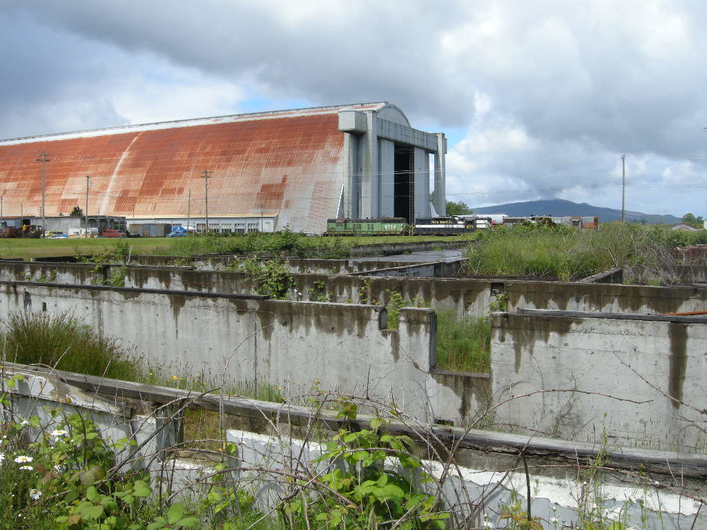
The Blimp Hangar, Naval Air Station Tillamook
Without considerable effort, the Guinness Book of World Records’ largest wooden structure, and the most extant naval air station from World War II is endanger of disappearing.

Port of Tillamook 2010 Preproprosal Meeting 061510 006
Commissioned in 1942 and operational through 1949, the Naval Air Station Tillamook (NAS) is a 1,600 acre site comprised of buildings, structures, landscape features, as well as a current active runway. A smaller 400 acre site has been designated an eligible historic district. The original use by the NAS Tillamook contained 32 defense, eight industrial, five government, four transportation, three commercial, three agricultural, three residential, two recreation and culture, one education, and one utilitarian structures, plus one cemetery. The most significant structures include the airfield, Hangars A & B, ammunition magazines, and structures that supported the operation of the Naval Air Station. Many of the buildings may be the only remaining example of their kind. Much of the site is still operational: the roads, sidewalks, water power sewer and utility lines, as well as the railroad infrastructure were constructed by the US Navy remain on site and are character defining features.

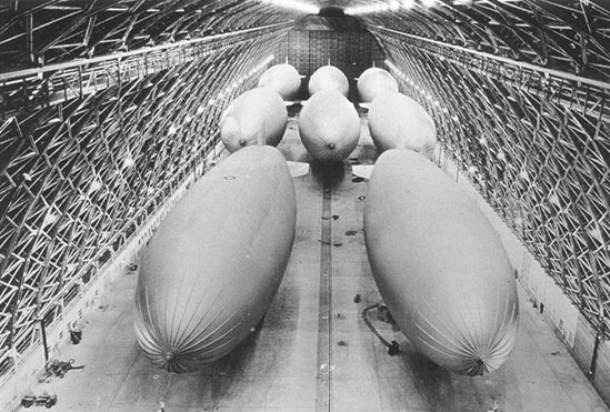
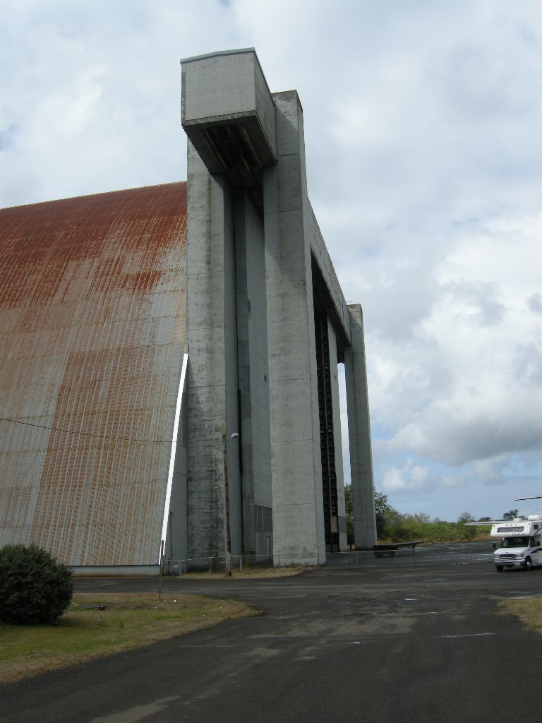
Hangars A & B were built for “K type” dirigibles that are steerable, non-rigid, lighter than air aircraft used for naval air patrol of enemy submarines. During World War II, the hangars served as mooring and maintenance sites for two squadrons of dirigibles that patrolled the coast line from the Strait of Juan de Fuca to California. A fire in 1992 destroyed Hangar A. The remaining U.S. Naval Air Station Dirigible Hangar B, is the world’s largest wooden clear-span structure measuring ¼ mile long and 23 stories in height. Its construction technique is considered both resourceful for war time efforts and an innovative structural solution. Incredibly, the hangar was completed in just 90 days.
POTB Blimp Hangars
Hangar B reflects the unique challenges associated with super-sized historic properties. Monumental historic properties pose significant management, maintenance, and financial challenges to the long-term stewardship of such properties. Aging infrastructure, 70 or more years of service-life, and limited lease markets for using enormous structures increasingly place pressures on the decisions to retain the resources. Despite the desire to be good stewards, large properties rarely generate sufficient funding to go beyond very basic emergency and/or minor piece meal repairs. Straight forward maintenance items, like new roofing or painting, can cost several million dollars.

POTB HanagarCreative, multi-jurisdictional, community involvement, private / public partnerships, government programs, and national and international marketing campaigns have become key elements to long range cultural resource management plans. The unique structures require innovative solutions matching the monumental character and commanding presence. Success stories abound from the saving of West Baden Springs Hotel in French Lick, Indiana to Centennial Hall in Wroclaw, Poland. The efforts to retain the giant structures are well deserved, because the continued loss of such buildings diminishes our understanding of world events.

To learn more about PMA’s experience at the Port of Tillamook Bay, please visit: PMA + PoTB


Written by Peter Meijer AIA, NCARB, Principal

Conservation: A Case Study between Art and Architecture

The Oregon State Capitol
The Oregon State Capitol is a landmark of Modernistic design based on Classical Architecture, and was designed by the New York architectural firm of Trowbridge and Livingston in association with Francis Keally. Completed at the height of the Depression in 1938, the Capitol received funding assistance from the Federal Emergency Administration of Public Works (P.W.A.). Constructed of reinforced concrete, the building is distinguished by angular, unadorned exterior elevations and a massive, ribbed lantern – all sheathed in brilliant white Vermont marble. Artists of national reputation, Ulric Ellerhusen, Leo Friedlander, Barry Faulkner, and Franck Schwarz, collaborated in the winning design and were employed at the recommendation of the architects to produce sculptural relief and paintings of a taut and finely wrought decorative program. Erected in the Modernistic style, the Capitol was sensitively enlarged in 1977 by the Portland firm of Wolff Zimmer Gunsul Frasca in association with Pietro Belluschi.
OR State Capitol Building
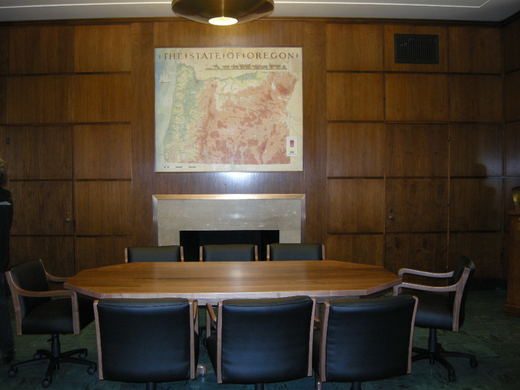
On Labor Day 2008, a construction fire damaged the exterior Vermont marble, interior Oregon walnut wood panels and a painting by Barry Faulkner adorning the Governor’s Ceremonial Suite. A team of preservation architects and art conservators collaborated to guide the faithful restoration of this important Oregon icon. All restoration work was based on historic research and field analysis of existing materials, but conservation principles were applied differently to the restoration of interior finishes compared to The State of Oregon artwork by Barry Faulkner.
OR State Capitol Fire Destruction Interior
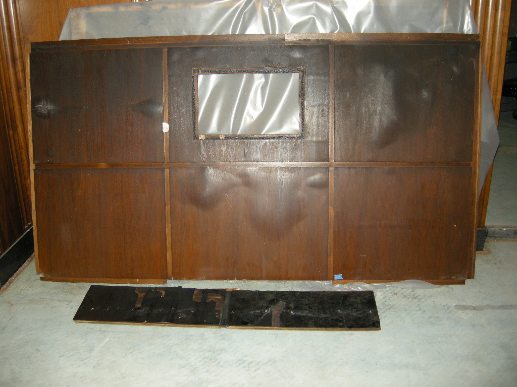
Fire destroyed all the wood panels on the south wall and caused extensive smoke and heat damage on the east and west walls. The north wall suffered minor smoke damage with little to no impact from heat. Oregon Walnut, a species of wood no longer readily available or milled, was incorporated into 30” x 30” veneer panels separated by 1” wide solid walnut splines. Each panel was book matched resulting in pairs of cathedrals providing strong visual character. It was determined through both field and laboratory testing that the original finish system was a shellac formula readily used during the late 1930s. Conservation strategies had to consider: proper dismantling techniques of the remaining panels; reproduction of original finishes using volatile compounds or the replacement with new finishes; repair options for the various degrees of damage to the wood panels, incorporation of new replacement panels, and anticipate potential similar catastrophic events in the future.
Restored OR State Capitol interior
The remaining panels were measured, documented and classified by the extent of damage. Drawings were produced that recorded each panels’ location relative to the adjacent panel and position on the wall and compass orientation. It was determined that each panel and spline were individually blind nailed to a wood lath support grid which was in turn directly fastened to a back-up clay tile wall. Remaining panel construction from the south wall provided evidence of the construction techniques. As a result, it was determined to the remove the panels in an assembly as large as practical for transportation to a controlled restoration shop environment. At the shop, a more thorough, up-close evaluation of the damage was surveyed. During review of the restoration options, discussion ensued over the incorporation of pre-existing conditions, post fire damage, to include evidence of repair, or should all the panels have a uniform appearance.

After considering the impossibility of achieving uniformity with new panels and cleaned and repaired panels, it was decided to remove all finishes, including the protective shellac, by sanding to bare wood. Following the removal process, each panel was stained to match a patina color visible on a panel protected from damage. The final clear coat was a catalyzed finish formulated to provide long-term protection.
Damaged OR State Capitol Art
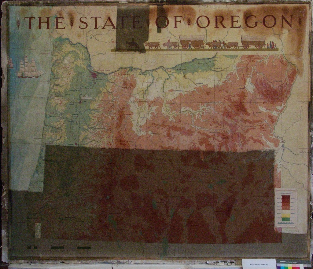
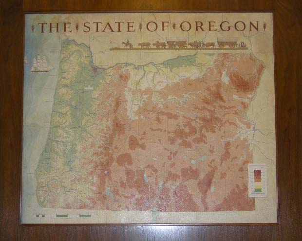
To further embellish the Governor’s Suite, a map of the State of Oregon was painted by Barry Faulkner, signed and dated in 1938. The work was framed within the wood paneling over the marble mantel on the ¬East end of the Governor’s Suite. Faulkner painted the work in oil on canvas that was subsequently marouflaged to a section of the wall. This section of the wall was clearly part of the original design of the room and was reserved and prepared especially for the painting. As was customary in New Deal era murals, Faulkner’s work was painted on canvas off site and then adhered to the wall when the construction process was advanced or complete. Also quite typical of New Deal murals was the use of a lead paste adhesive for the marouflage, which was suggested in the later W.P.A project guidelines to the artists. The presence of the lead paste adhesive proved to be decisive in the formulation of a method for the deinstallation of the piece. The tenacity of the adhesion of the canvas back to the plaster via the lead paste is such that separation of the canvas from the plaster was impossible, and so the entire section of wall needed to be removed intact for the conservation treatment. The section of wood framing was carefully removed from the clay tile wall substrate by severing the nails that fastened the wood to the tile, and cutting the vertical studs above and below the work. Special precautions were made to protect the fragile paint surface during transport of the work to the conservation lab.
Damaged OR State Capitol art detail
The fire’s effects caused extreme heat damage to the painting primarily in the upper and right areas of the composition, with numerous areas of blistered paint, and many sections of blistered delamination of the canvas from the substrate plaster. The combustible by-products of the fire combined with embedded soot and smoke created a deposited layer of darkened material that obscured the image. The solubility testing results were consistent with the combustible origin of the fire, and a solution of organic solvents was used to remove the deposited surface material, revealing the original chromatic palette of the work. It also became evident that the painting had been cleaned in a previous treatment. The fragile areas of heat-blistered paint were consolidated and smoothed. The areas of blistered delamination were brought back into plane with localized use of humidity and mild head and then, once smoothed into place, were adhered to the substrate plaster. The large blister in the upper right corner of the painting protruded 1 ½” from the plaster surface. Areas of loss were filled, textured and retouched to match the original surface and color. A protective layer of varnish was applied to the painting.

The exposed finish plaster surrounding the painting was also cleaned with dry sponges, consolidated and filled. Some original pencil drawings by the artist were found on the plaster that had been hidden under the paneled frame.
restored OR State Capitol art detial
The most extreme heat damaged areas were irreversibly altered in both their color and texture, and the full extent of the color shift was not revealed until after the cleaning process. In these darkened areas, Gamblin conservation colors were applied over the varnish layer to retouch the creamy yellow ground color only, leaving the darkened red color of the letters in THE STATE OF OREGON untouched. This manner of retouching allowed the painting to acquire a more finished appearance in line with the decisions made regarding the restoration of the wood paneling, while conserving also the memory of the history of the piece.


Written by Peter Meijer AIA, NCARB, Principal. A special thanks to Nina Olsson, Nina Olsson Art Conservation, LLC, who helped write this post in conjunction with Peter Meijer. Nina Olsson Art Conservation , LLC is a private practice for the conservation of paintings and polychrome sculpture based in Portland, Oregon.

Water Intrusion: The Technique of a Leak

With patience, persistence, and a methodical process, water intrusion defects can be
located and repaired.

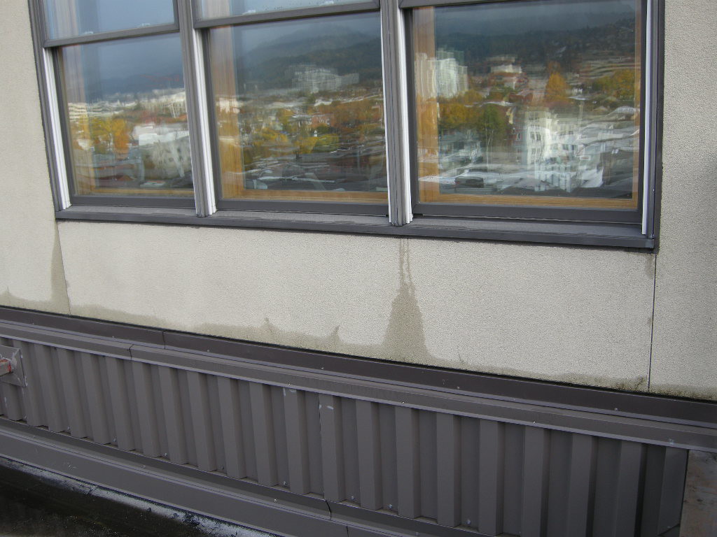
Finding the source of water intrusion within an older existing building can be exceedingly frustrating. Following a methodical and systematic investigation procedure will manage and organize the process. If the leak is occurring within occupied space, it is critical to interview and obtain information from those individuals directly affected by the circumstance. Is the leak associated with weather, water use, or other activities? If weather related, when did the leak occur relative to the start of the bad weather? Does the leak occur under windy conditions only? Wind driven rain can push water 2 inches up a vertical surface. Does the leak occur consistently in the same spot? Having an understanding of the building’s age, material science, archaic construction techniques, and professional experience brings focus to the investigation.
MW Loft water intrusion PMAPDX
Visual observation is the single most important diagnostic tool. Are there obvious sources of water intrusion like open windows, broken downspouts, exterior holes in the building shell, or leaking bathroom fixtures? Storm days are often good opportunities to observe the flow of water over a building surface leading to potential sources. After a rain storm, are some exterior surfaces slower to dry? Has the water pooled along horizontal surfaces or against exterior walls? These observations can be made directly by the investigation team or related by maintenance personnel or property owners. Photographs taken before, during, and after a leak provide valuable perspective on the dynamic nature of the leak.

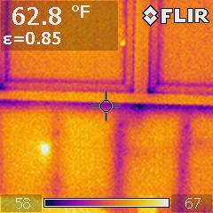
Infaread testingInfrared camera analysis adds another diagnostic layer of evaluation data. Temperature differentials between wet and dry surfaces can collaborate other visual observations. However, a number of varying conditions, not just water, can cause temperature differences between materials or even temperature differences within the same material. For instance, an exterior stucco wall installed over steel studs may have extreme temperature changes as a result of heat conductance through the steel studs with no related water intrusion.
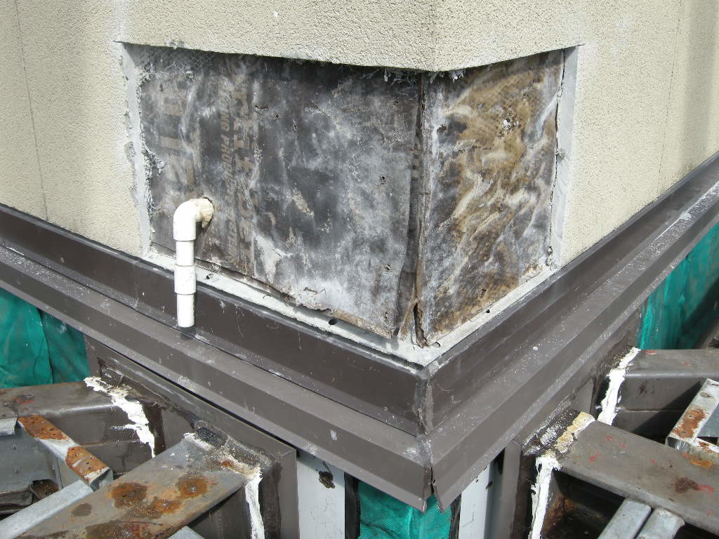

Often it becomes necessary to augment general observations of interior and exterior surfaces with destructive investigation, a method by which the surface materials are sequentially removed to investigate archaic construction methods. As materials are removed, construction techniques can be evaluated for water tight joints. Moisture meters and other hand-held evaluation tools verify the presence of defective conditions. Openings, or wall-lets, are located at corners, abutting materials, complex intersections of structural elements and architectural materials, and/or other commonly known sources of water intrusion.
MW Loft Stucco repair PMAPDX
Reverse investigation in which the leak point is enlarged and video scopes or wires or other tracing devices are inserted in the opening are used to back trace the leak from the point of observation to the source. This method is often a last resort because it involves cutting several observation points in all directions to follow the path of water.


Written by Peter Meijer AIA,NCARB, Principal