Tag Archives: building enclosure design

Inherent Sustainability of Historic Architecture

Trinty-Episcopal-Church-pmapdx

The terms ‘Sustainability’, ‘Green Building’, ‘Environmental Design’, and other similar phrases have recently become critical in how we approach and understand contemporary architecture. As concerns over pollution, global warming, and our impact on the surrounding environment have gained traction – we have begun to understand the building industry’s contribution to these issues. The US Green Building Council reports that buildings account for 39% of all carbon emissions in the United States, surpassing both industry and transportation.

At the core of the issue is how architects, clients, and the public imagine buildings should function and operate; a vision which has transformed over the last two centuries as technological advances have developed the capabilities of the building industry. In the last two centuries, buildings have become monuments to the Industrial and Technological Revolutions. The development of electrification, central heating, air conditioning, steel and concrete have transformed how architects design and how users function within the built environment. This shift has transformed architecture from an inherently sustainable practice into a much more complex and often unresponsive process.

While the phrase ‘sustainability’ has only recently been associated with architecture, many historic buildings were designed by incorporating sustainable practices. Without electricity, buildings by necessity had to respond to site orientation and the local climate. Natural ventilation was used to passively cool buildings, well placed windows provided natural light, and construction methods varied by location to provide an appropriate level of protection from the surrounding environment. However, as a result of modern renovations, these sustainable attributes are not always utilized to their fullest potential.

Historically, large, operable windows were an integral component of architecture in moderate climates like the Pacific Northwest. The glazing provided natural daylight while the operability allowed users to ventilate spaces based on thermal comfort. Today, the operability of windows in many historic buildings has been compromised for a variety of reasons:

• Windows that have been fixed shut to prevent users from overriding the central air system.
• Broken window hardware that hasn’t been properly maintained.
• Windows that have been painted shut.
• Windows that have been fixed shut to minimize maintenance.

Without the natural ventilation that was incorporated into the original design, these historic structures often overheat and/or rely heavily on central air conditioning. One must question why the inherent sustainability of these historic structures was compromised. Was it simply our initial infatuation with mechanical heating/cooling systems? As passive sustainable design gains traction it is critical that we understand the capabilities of historic structures in regards to their inherent sustainability.

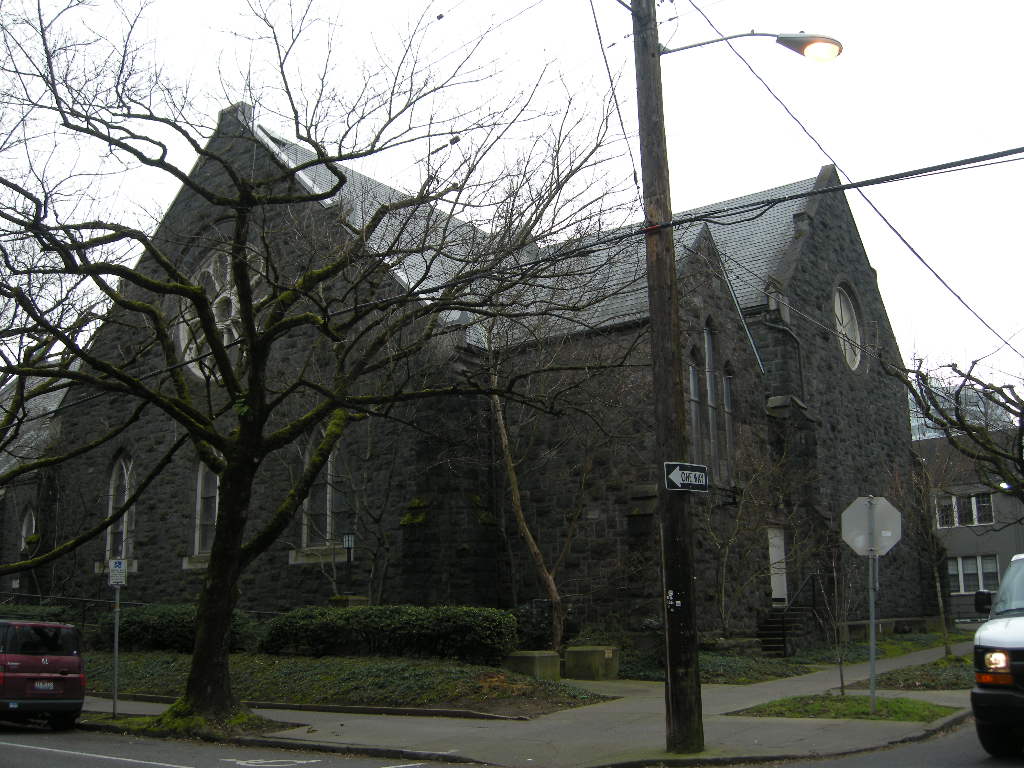
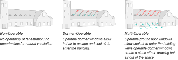
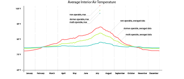
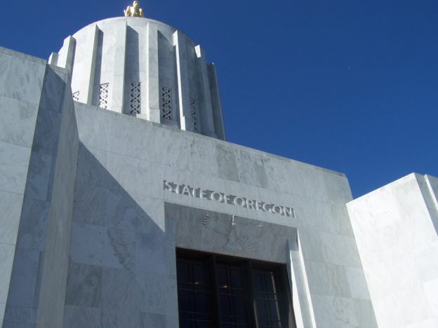
For further investigation we have identified a case study that explores the possible impact reintegrating natural ventilation may have on thermal comfort. Trinity Episcopal Cathedral in Portland, Oregon was built in 1906 and the original design included 10 operable dormers along the Sanctuary roof. The dormers have since been boarded over, preventing rising heat from escaping. Congregants find the space overheated during the summer months and one must question whether operable dormers would provide adequate ventilation to sufficiently cool the space.

An energy model has been developed using OpenStudio and EnergyPlus to compare the thermal comfort of occupants within the space. A baseline model mimics the existing conditions and provides a comparison for the two different natural ventilation configurations. One natural ventilation configuration re-introduces the operable roof dormers to vent hot rising air. The other natural ventilation configuration re-introduces the operable roof dormers and integrates additional ventilation at the exterior wall of the building to produce stack ventilation.
Trinity Results-wufi-pmapdx

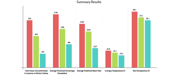
While the project is still in process, initial results indicate that natural ventilation could have a significant impact on the space. The study has focused on the thermal comfort within the Sanctuary and results show that natural ventilation could dramatically lower indoor temperatures during peak summer months.

Trinity Results-wufi-pmapdx

Trinity Results-wufi-pmapdx

The results continue to be fine-tuned, and further refinement of the energy model will include:

• Adjusting schedules/systems to more closely reflect the building’s occupancy.
• More accurately defining the exterior infiltration rates.
• Exploring more relevant solutions for integrating stack ventilation that don’t require the large operable exterior windows. For example integrating ventilation through the basement into the main sanctuary.

While further research remains to be done, initial results are promising and demonstrate the inherent sustainability of the structure. While each building is unique, this Case Study shows how reintegration of natural ventilation may be a viable solution for passive cooling in uncomfortably warm historic buildings. Continue to check back for updates as we refine our study and explore how re-integration of natural ventilation may result in energy savings!

Written by Halla Hoffer, Architect I

UW Denny Hall Renovation

Denny Hall was built in 1895 and was the first building constructed on the current University of Washington campus. Peter Meijer Architect, PC (PMA) conducted a full exterior envelope assessment and full window survey on this historically significant building in anticipation for renovation.

The assessment included terra-cotta and masonry attachment investigation, decorative iron work assessment and mortar petrographic examination. The window survey of the multi-paned steel sashes, the installation of which occurred during a campus-wide 1950 upgrade, provided information allowing the University and design team to retain the character defining features.

Additionally, PMA guided the design team on repair of the existing sandstone entry stairs and provided information on the “hidden” header course, which was a key factor in reducing the need and expense for further seismic anchors.

Mercy Corps North Facade (Viewing Southeast)

Mercy Corps World Headquarters Renovation

The historic Packer Scott building, now the World Headquarters for Mercy Corps, had significant damage to the original masonry resulting from inappropriate sand blasting cleaning techniques. PMA provided a complete building exterior assessment and identified areas of 50% or more cross section loss to the masonry and guided the design team towards suitable replacement material. In addition, PMA investigated foundation drainage issues during construction using non-destructive investigation techniques, and worked with the sub-contractors to provide proper techniques in the use of lime-based mortar.

Building Envelope Corrections:
• Analysis of exterior masonry and identification and specification of proper repair material and techniques.
• Analysis of the original construction means and methods of the sheet metal entablature as well as techniques for repair.
• Conducting full building window assessment and development of the drawings and package leading to support for window replacement.

PMAPDX-Meir-Frank-Building-Envelope

Meier & Frank Warehouse Renovation: Vestas HQ

Peter Meijer Architect, PC (PMA) was the Historic Preservation Architect for the full restoration of the 160,000 square-foot Meier & Frank warehouse to office conversion for Vestas Headquarters, a wind turbine developer. Built in 1928, the renovation added a penthouse with ecoroof and outdoor gathering spaces to the original four story structure. For the renovation, PMA provided:

• Building condition assessment
• Analysis for the repair and design
• Construction documents

Additionally, PMA completed a limited exterior assessment of the roof for the added penthouse at the Meier & Frank building. The deficiencies noted at the penthouse level were similar in nature to the deficiencies at the lower elevations. The building is LEED platinum.

The Meier & Frank [Warehouse] built in 1927, was designed by the noted Portland architectural firm of Sutton and Whitney. The restoration of the Meier & Frank Warehouse required the evaluation and repair of extensive concrete cracking, replacement of reinforcing bar, and detail drawings suggesting the construction of repair concrete form work.

PMAPDX-oregon-State-Capitol

Oregon State Capitol Building Fire Restoration

The Oregon State Capitol was designed by the New York architectural firm of Trowbridge and Livingston in association with Francis Keally and completed in 1938. Erected in the Modernistic style, the Capitol was sensitively enlarged in 1977 by the Portland firm of Wolff Zimmer Gunsul Frasca in association with Pietro Belluschi. Constructed of reinforced concrete, the building is distinguished by angular, unadorned exterior elevations and a massive, ribbed lantern all sheathed in brilliant white Vermont marble.

In 2008, as part of the team creating a new Master Plan for the Capitol, PMA conducted a full exterior condition assessment of both the main building and east and west wings. On Labor Day 2008, an exterior fire damaged the Vermont marble and Oregon walnut interior panels adorning the Governor’s Ceremonial Suite. PMA was retained to guide the faithful restoration of this important Oregon icon.

Due to the third fire in the Oregon State Capitol’s history, the Governor’s Ceremonial Suite required complete restoration and renovation. PMA provided restoration documents for the repair and replacement of exterior marble, repair of interior walnut paneling, reinstallation of linoleum flooring, reintroduction of historic carpet, integration of preservation of historic materials, and the repair of plaster ceiling and walls. Additionally, PMA provided guidance to the conservationists repairing the WPA painting, which was also damaged. All restoration work was based on historic research and field analysis of existing materials.

When A Master Work Fails: Three Case Studies

Some of the greatest restoration challenges arise when historically significant works weather, degrade, are neglected, or simply have suffered through inappropriate renovations. Restoration strategies are compounded when original historic materials, either natural materials like wood or stone, or production processes are no longer available. And when the failure is due to improper design or inadequate construction methods, corrective restoration methods may alter or compromise the original design intent. The following three case studies illustrate restoration philosophies based on balancing preservation, resolving the underlying building deficiencies, and introducing “thoughtful change” in protecting significant local structures for future generations.
John Yeon 2012 004
Case Study 1
John Yeon’s 1948 Portland Visitors Centerwas designed as an exhibition showroom with large open spaces, a pinwheel plan, on a highway dividing median, accessible by car, and constructed of standardized wood framing components including recently developed experimental plywood. When the highway was replaced with a riverfront park and the Visitor Center programming was relocated, the singular purpose building became obsolete resulting in a number of incompatible conversions including substantial alteration of the main gallery space to an industrial kitchen. Contributing to the slow demise was the degradation of the exterior wood components and failure of the plywood as a result of the northwest climate and inadequate weather protection. By the time the Friends of John Yeon and the City of Portland Water Bureau invested resources into the restoration, the Visitor Center had lost or compromised 80% of its historic interior finishes and the exterior façade had been heavily altered. However, the original floor plan, massing, scale, exterior spaces, and essence of Yeon’s modular design and sense of place remained.
WS Scheme 3 Entrance 101209Space programming respected the historic floor plan and scale of the original structure and recreated Yeon’s original design intent of integrating indoor space with outdoor space. Extraneous equipment and unsympathetic additions were removed from both the interior and exterior. Interior design elements, furniture, and fixtures maintain the open gallery spacial quality while integrating new furniture and fixtures meeting the needs of the tenant. Major preservation focused on the exterior restoring original paint colors through serration studies, restoring building signage in original type style and design, preserving original wood windows, when present, and restoring the intimate courtyard with a restored operating water feature.

Case Study 2
120907 Lovejoy Pavillion 002
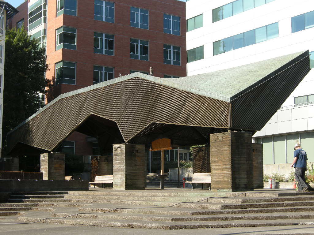
Moore, Lyndon, Turnbull & Whitaker’s 1965 Pavilion at Lawrence Halprin’s Lovejoy Fountain is a whimsical all wood structure with a copper shingle roof. Although a small structure, the pavilion represents a major mid-transitional work for Charles Moore as his design style moved from mid-century modern to Post-modern design. In keeping with the naturalistic design aesthetic established by Halprin, northwest wood species comprise the major structural system including the roof trusses, vertical post supports, and vertical cribs built from 2 x 4 members laid on their side and stacked.

Vertical loads are transferred from the trusses to the wood posts and spread to the wood cribs. Under the point loading, the cribs have compressed resulting in a sag or lean in the roof structure. Since the 2 x 4 wood members have crushed, they cannot be restored or salvaged as part of the restoration effort so new members were designed to replace the historic material.

120907 Lovejoy Pavillion 009
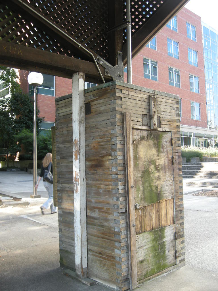
The restoration approach is intended to correct the structural deficiencies and replace the failed members with no changes to the historic appearance of the structure. The crib design allows for insertion of new steel elements, invisible from the exterior, capable of providing additional support for vertical loads. The difficulty arises because standard wood products available today have different visible and strength attributes from standard components available in 1965. Sourcing appropriate lumber is dependent upon clear and quantifiable specification, high quality inspection, and visual qualities. There are no structural standards for reclaimed or recycled lumber compounding the incorporation of “old growth” lumber as part of a new structural system. When original source material is no longer available, best practices for narrowing the selection of new materials will of necessity be combined with subjective visual qualities and a best-guess scenario as to how the new material will age in place similarly to the historic material. There are no single solutions so experience is key.

PMAPDX-survey-city-of-portlandCase Study 3
Whether or not Michael Graves’ Portland Building is considered a master work is greatly debated. Never the less, the building was nominated to the National Register of Historic Places after only 30 years and is recognizable around the world as THE building representing the start of Post Modernism. There is no debate to the fact that the building leaks. However, the method of building envelope repair could dramatically or minimally impact the exterior character defining features.

The façade of the Portland Building incorporates standardized aluminum single unit windows, aluminum windows ganged together to form a curtain wall, ceramic tile, and stucco veneer as the prominent construction materials. All of these systems or individual components are neither produced nor assembled currently in similar manners due to improvements in technology and building envelope science.

Proposals to improve envelop performance of both the individual window units and window systems are challenged in finding products that will both improve performance and retain the aesthetics of a Post Modern building. (i.e. retain the essence of criticism towards Post Modernism by preserving the appearance of insubstantial material installed as a thin veneer). Windows have always been a source of controversy in preservation and now the definition of windows has expanded to include curtain wall systems as the importance of preserving Recent Past and Modernism has entered into the mainstream.

When a structure, like the Portland Building, relies heavily on the expression of its skin as the character defining feature, off the shelf solutions for fixing envelop deficiencies must be expanded to include customization, façade impact studies, robust strategies for solving the issue, and out-of-the-box thinking by conservators, architects, historic consultants, and building envelope experts. A collaborative approach based on the original architect’s design intent must drive the decision making. It is an unusual approach, but original design intent will be a key factor when resolving façade problems on Modern and Post Modern structures.

Written by Peter Meijer AIA,NCARB, Principal
portlandbuilding-model

Burnt Clay Facades

Terra cotta, or “burnt clay,” is a hard baked, high grade of weathered or aged clay. It is similar to brick but the clay is of higher quality and fired at higher temperatures. This article focuses on exterior architectural terra cotta as distinguished from statuary, pottery , and terra cotta blocks used as inner wythes of wall or fill material.
300px-Court_of_Honor_and_Grand_Basin
The 1893 Columbian Exposition in Chicago demonstrated the versatility and ornamental qualities of terra cotta. It highlighted the great variance in color and shapes possible with terra cotta and began the demand in the United States for terra cotta that lasted through the late 1930s. Terra cotta is prized for its light weight, longevity, aesthetic qualities, and unit construction. At the peak of production, almost every urban area in America was producing architectural terra cotta in some variation. Today, most replacement units are produced by either Gladding McBean or Boston Valley Terra Cotta.

Specific forming techniques including hand press, machine press, slip casting, and extrusion are used depending on the shape and style of unit required. In the analysis of terra cotta failure the forming techniques are less critical than the strength characteristics of the fired clay, the integrity of the exterior surfaces, and structural support systems.
Boston Valley new TC
Exterior ornamental terra cotta was marketed as a light weight water proof cladding. And if proper construction techniques were employed, and the system was maintained, and the local climates were mild, terra cotta performed as sold. However, terra cotta adorns buildings in severe weather climates, and is installed with structural materials affected by environmental conditions, and located on façade elements inaccessible for routine maintenance.

The mortar joints are the material most susceptible to failure. Joints often exist on all three axis with some units of terra cotta designed for flat horizontal surfaces. Over time and exposure, the mortar fails providing a means for water intrusion. Sever cycling of weather in simultaneous freeze/thaw conditions can cause the terra cotta clay to expand and contract, accelerating the crazing or cracking of the protective glaze. Extensive crazing can lead to glaze spalling and allow for further water intrusion.

Once water enters the system there is no weep path allowing for water egress. Construction means and methods, as well as the cellular unit design, trap water and contribute to the potential corrosion of steel lintels, wire ties, steel structural support members, and other miscellaneous metals. Rapid freezing and thawing cycles, in addition to steel corrosion, can crack terra cotta units. If the units remain unrepaired, further water intrusion and/or absorption will occur.
121022 QAHS S Elev 094
The repair of terra cotta will depend both on the cause and manifestation of the defect. Typical defects include crazing of the glazed finish, shallow surface spalls, deep spalls affecting the bisque, cracked units, inadequate support and / or anchorage, corrosion induced stress fractures, impact damage, mortar degradation, lack of maintenance, and inadequate repairs.

Proper terra cotta repair methods are linked to the cause of defect. Repair techniques are often performed on-site by skilled tradesmen. When damage to the terra cotta unit is severe, full replacement may be required. Defects due to inadequate support or a result of corrosion to supporting steel members is likely to require more invasive repair strategies including removal and replacement of several courses of interlocked terra cotta units.

QAHSC
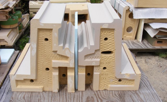
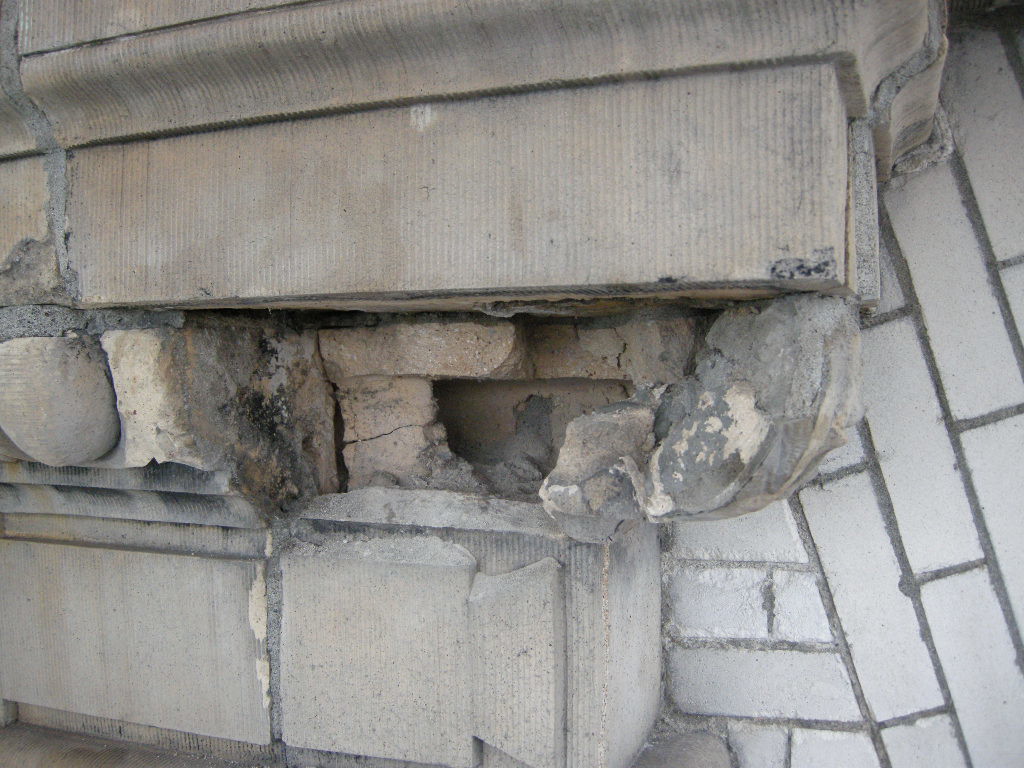
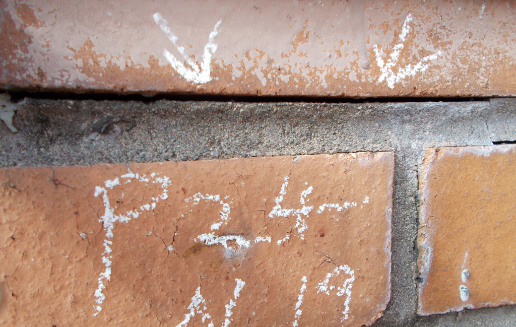
When replacement units are not required and the scope is limited to on-site repair, labor costs exceed material costs. Since many historic terra cotta units were specialty designed and installed for the structure, a premium price is paid for replacement. New exterior decorative terra cotta is available only from the sources referenced and with small quantity orders, the first unit is approximately $5,000 with much of the costs attributed to making the form and determining the finish color and texture. Subsequent costs per unit will decrease with the range of decrease dependent upon quantities required.

The most important component of terra cotta repair is an understanding the cause of deterioration and the proper repair specifications. Both are derived after a full condition assessment and evaluation of the existing conditions.


Written by Peter Meijer AIA, NCARB, Principal


——————–
Sources
• Last of the Handmade Buildings, Virginia Guest Ferriday, Mark Publishing Co., Portland, OR 1984
• National Park Service, Preservation Brief No7, Preservation of Glazed Terra Cotta
• APT Pacific NW Chapter 2005 workshop
• Terra Cotta, Standard Construction, Revised Ed., National Terra Cotta Society, 1927

The Challenges of Assessing Structural Brick Veneer Panels

The origin of Structural Brick Veneer Panel dates back to the early sixties when new “tensile strength intensive” exotic mortar combined with steel reinforcing to create a 4-inch thick, single wythe brick panel. Developments continued to occur throughout the 1960s and 1970s, peaking in use during the 1980s. The system was relatively expensive due to the use of the high tensile strength mortar.
Koin Center brick pane
Developments in both the high tensile strength mortar and the clay units continued to reduce cost and allow the use of regular reinforcing and standard mortar and grout. Newer systems and manufacturing processes accommodated both horizontal and vertical reinforcing and permitted high-lift grouting. Later advancements in the connections of the brick veneer panel system to the building frame resulted in the use of brick veneer panels system on multi-story high-rise office buildings, schools, apartment buildings, residences and many other applications throughout the United States and the Pacific Northwest.
cracked brick_design guide
Major Failure Mechanisms
There are two major failure mechanisms of Structural Brick Veneer Panels: water intrusion and mortar/grout additives. Water intrusion can occur from a lack of adequate flashing at the window head and sill interface, carbonization of the mortar, and structural cracking. Brick veneer panels are commonly designed to allow for limited cracking at the horizontal bed joints at the brick to mortar interface. Masonry veneer panels leak more through the mortar and brick interface than through the masonry unit itself. If the mortar and brick interface is cracked, as is permitted under structural design calculations, water infiltration will increase. A cement based material, panel mortar will carbonize over time decreasing the protective alkalinity environment surrounding the reinforcing bar and thus increasing the potential for corrosion. The largest volume of water intrusion is typically associated with inadequate window systems that fail to keep water out of both the structural brick veneer panel and the cavity interface.
024
The durability of the wall is highly influenced by the quality of the mortar joints and interior cell grout. The specification should require reconsolidation of the grout or the incorporation of additives that balance expanding, retarding, and water reducing agents to provide a slow, controlled expansion prior to the grout hardening. Mortar/grout additives, particularly those developed in the 1970s, containing vinylidene chloride can initiate and accelerate reinforcing steel corrosion under the right conditions. The composition of the mortar/grout is determined through laboratory analysis of chloride content, vinylidene chloride, and pH level.

Repairs to structural brick veneer panels is labor intensive and may involve panel replacement, panel encapsulation, window system replacement, and/or extensive individual masonry unit repair.


Written by Peter Meijer AIA,NCARB, Principal
—————

Acknowledgement: Tawresey, John G. & John M. Hochwalt, KPFF Structural Engineers, Design Guide for Structural Brick Veneer, 3rd Ed, Western State Clay Products Association

Water Intrusion: The Technique of a Leak

With patience, persistence, and a methodical process, water intrusion defects can be
located and repaired.

Finding the source of water intrusion within an older existing building can be exceedingly frustrating. Following a methodical and systematic investigation procedure will manage and organize the process. If the leak is occurring within occupied space, it is critical to interview and obtain information from those individuals directly affected by the circumstance. Is the leak associated with weather, water use, or other activities? If weather related, when did the leak occur relative to the start of the bad weather? Does the leak occur under windy conditions only? Wind driven rain can push water 2 inches up a vertical surface. Does the leak occur consistently in the same spot? Having an understanding of the building’s age, material science, archaic construction techniques, and professional experience brings focus to the investigation.
MW Loft water intrusion PMAPDX
Visual observation is the single most important diagnostic tool. Are there obvious sources of water intrusion like open windows, broken downspouts, exterior holes in the building shell, or leaking bathroom fixtures? Storm days are often good opportunities to observe the flow of water over a building surface leading to potential sources. After a rain storm, are some exterior surfaces slower to dry? Has the water pooled along horizontal surfaces or against exterior walls? These observations can be made directly by the investigation team or related by maintenance personnel or property owners. Photographs taken before, during, and after a leak provide valuable perspective on the dynamic nature of the leak.

Infaread testing
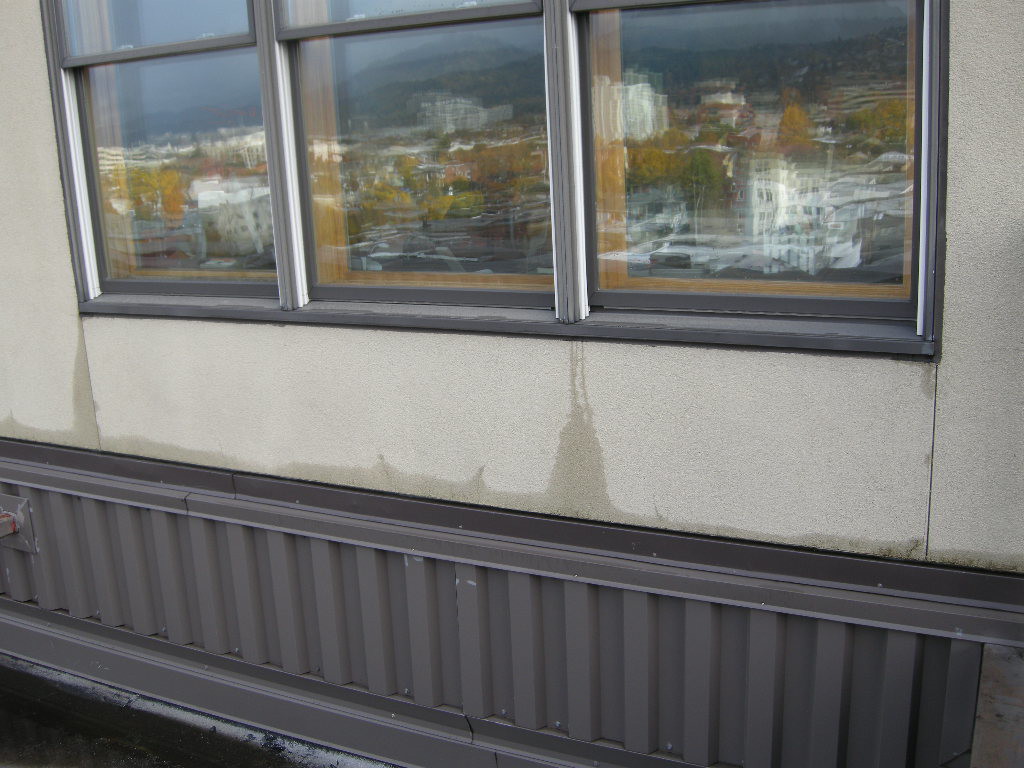
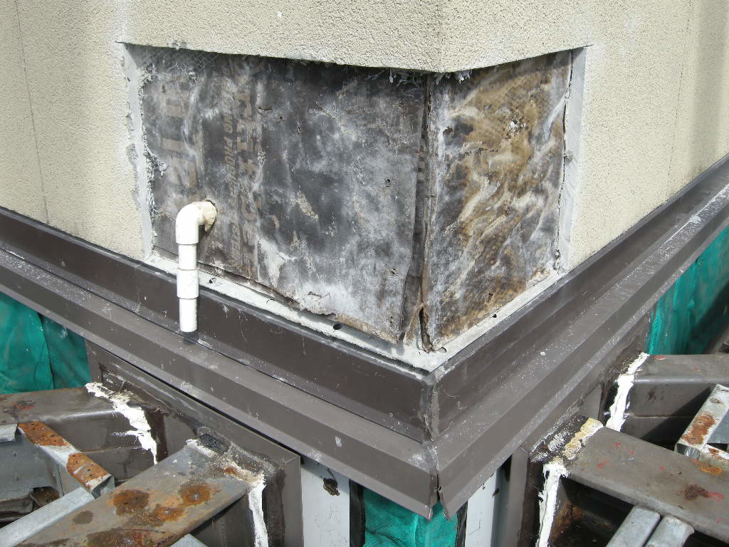
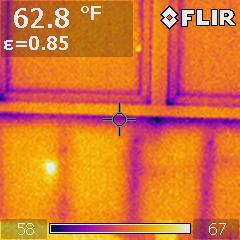
Infrared camera analysis adds another diagnostic layer of evaluation data. Temperature differentials between wet and dry surfaces can collaborate other visual observations. However, a number of varying conditions, not just water, can cause temperature differences between materials or even temperature differences within the same material. For instance, an exterior stucco wall installed over steel studs may have extreme temperature changes as a result of heat conductance through the steel studs with no related water intrusion.


Often it becomes necessary to augment general observations of interior and exterior surfaces with destructive investigation, a method by which the surface materials are sequentially removed to investigate archaic construction methods. As materials are removed, construction techniques can be evaluated for water tight joints. Moisture meters and other hand-held evaluation tools verify the presence of defective conditions. Openings, or wall-lets, are located at corners, abutting materials, complex intersections of structural elements and architectural materials, and/or other commonly known sources of water intrusion.
MW Loft Stucco repair PMAPDX
Reverse investigation in which the leak point is enlarged and video scopes or wires or other tracing devices are inserted in the opening are used to back trace the leak from the point of observation to the source. This method is often a last resort because it involves cutting several observation points in all directions to follow the path of water.


Written by Peter Meijer AIA,NCARB, Principal