Product X works as a masonry sealer, but what are the long-term ramifications of using Product X on masonry buildings? Masonry sealers come in a wide variety of formulations, but how do the various chemical compositions react to environmental conditions and what affect does the formulation have on the masonry? Most masonry waterproofing sealers specified by architects and conservators, installed by contractors, and requested by property owners are based on Silicone (═Si═ ) chemistry. There are three popular groups of silicone based materials being used as waterproofing materials: 1) silicates, 2) the group of silane, siloxane, siliconate; and 3) silicones. Silicates, similar to Product X, provide waterproofing properties by filling the pore structure of building materials with silicon dioxide (SiO2) precipitation. Common silicates are sand, Portland cement, and other natural occurring minerals. Silanes, siloxanes and siliconates provide waterproofing properties by bonding with the substrate. They are often referred to as penetrating sealers. Silicones do not form chemical bonds with the substrate. Silicones provide waterproofing properties by forming a non-bonded film. Such products are labeled as thin-film sealers.
SILICATES
Silicates are most commonly used in crystalline type water proofing agents for concrete. Their use is generally focused on concrete substrates. However, it is known that strongly alkaline, aqueous solutions of methyl silicates can be used to impregnate masonry. Such solutions often depend upon caustic soda for their alkalinity. Impregnation of masonry with such solutions is often disadvantageous, however, particularly due to the high alkalinity. For example, the high caustic soda content of the solution will cause a gradual removal of the organosilicon compounds from the interstices of the masonry by chemical combination with the surfaces of the masonry surrounding the interstitial voids. Moreover, the caustic soda solution reacts with carbon dioxide or other acidic components of the air which gives rise to salting out and the formation of efflorescence on the masonry. (1)
SILANE, SILOXANE, SILCONATES
Silane, siloxane, silconates are penetrating type of sealants. Their effectiveness is dependend on the porosity of the substrate and the dosage of repellant applied. Each manufacturer will have unique requirements for the application and dwell time of their sealer. Silanes and siloxanes form a chemical bond with siliceous containing materials. Silanes and siloxanes go through three reactions when applied to a masonry surface: hydroloysis, condensation, and bonding. During the condensation phase, the moisture vapor transmission rate is critical to preventing moisture accumulation behind the sealer layer.
With penetration type sealers, it is critical to the longevity of substrate (masonry) that the moisture vapor transmission of the sealer is actually known. There has been very little third party testing of vapor transmission and each product manufacturer provides varying ways of testing transmission. In addition, the active ingredient content of the sealer formulation and the coverage rate will greatly affect the moisture vapor transmission. In other words, performance in the field will vary greatly from highly controlled laboratory testing.
Siliconates are water soluble and they impart water repellency on porous surfaces. A drawback to using diluted siliconate solution for waterproofing applications is that siliconates react with carbon dioxide and carbonatious matters present in the substrate to form a water repellent, water-insoluble, white colored precipitate. This white layer may become quite visible and require aggressive removal procedures resulting in objectionable appearance or scarification of the surface during removal processes.
SILICONE
The effectiveness of silicone sealer depends on the alkyl group used (which directly influences its resistance to alkaline conditions), the amount of exposure to ultraviolet light and the level of moisture in the masonry when the silicone is applied. (2)
The proliferation of masonry coatings on the market, and the continued pervasive use of the coatings, requires the architect, engineer, contractor, and conservator become more knowledgeable on the wide variety of coating formulations, the continued evolution of those formulations, and understand both the right application of the product and potential detrimental effects of using the wrong product on historic substrates.
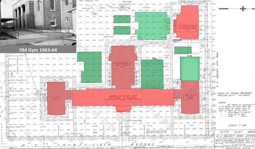
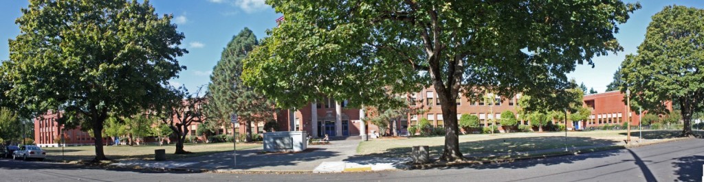
CASE STUDY: WASHINGTON STATE UNIVERSITY, DUNCAN DUNN HALL
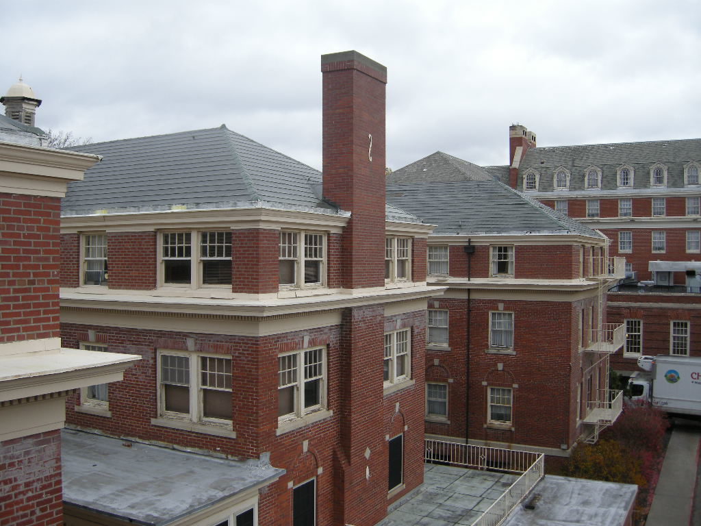
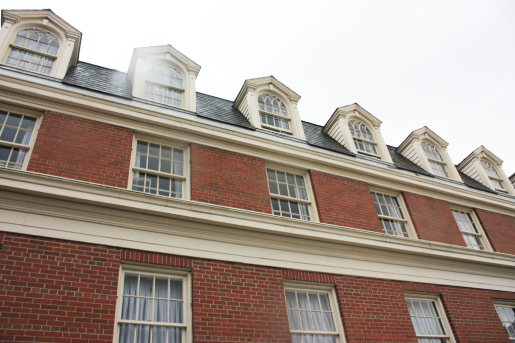
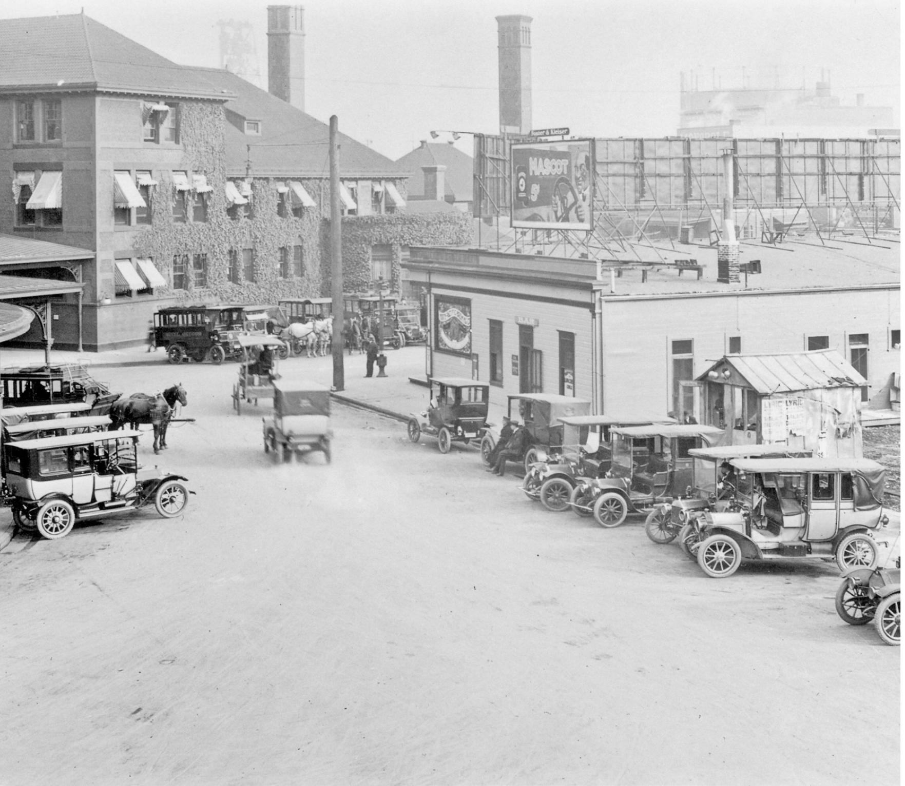
In preparation of a major renovation, Peter Meijer Architect, PC was retained in 2010 to conduct a general exterior condition assessment of Duncan Dunn Hall on the campus of Washington State University, Pullman, Washington.
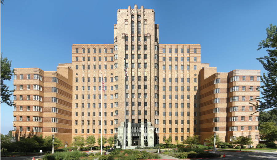
Duncan Dunn was constructed in 1926 as a women’s dormitory for Washington State University, then named Washington State College. It is located in the heart of the WSU campus, facing north towards Linden Avenue. First known as the “New Dorm,” the building cost $150,000.00 to build at that time, and could house 140 students. The architect, Stanley Smith, was the head of the department of architectural engineering and was also the official University Architect.
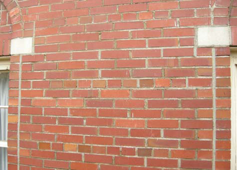
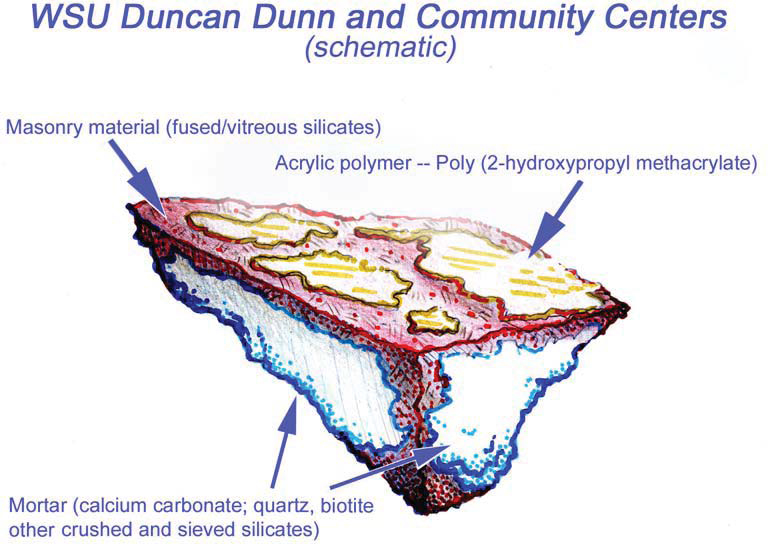
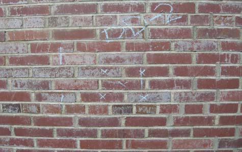
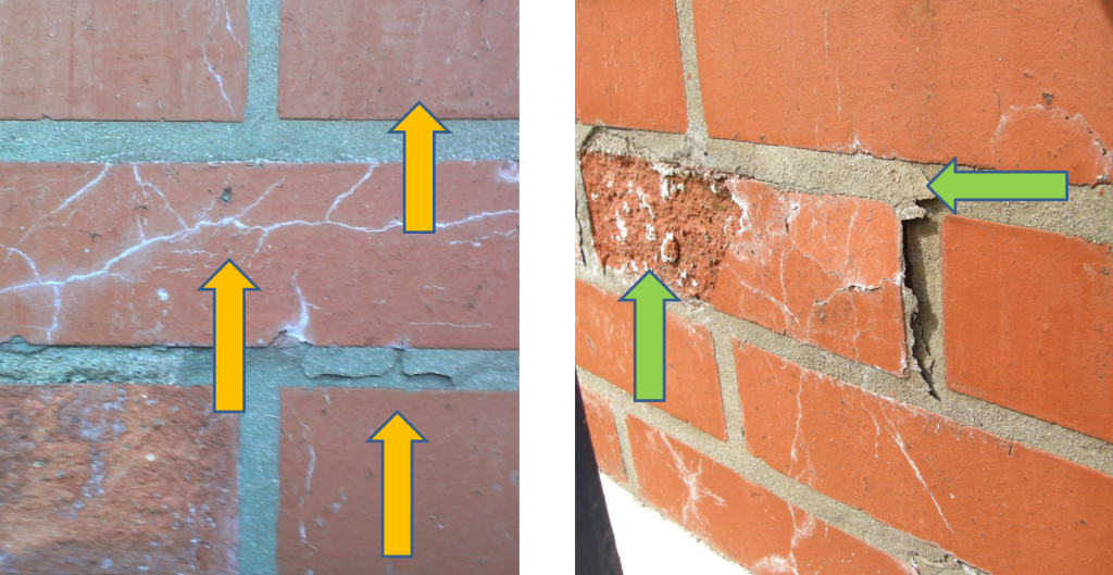
The predominant material present on Duncan Dunn is a solid brick unit, brownish red in color, and approximately 8” x 3 7/8” x 2 3/8” in size. At the time of assessment the brick had a very prominent unsightly, white coating over 60% of the masonry facades.
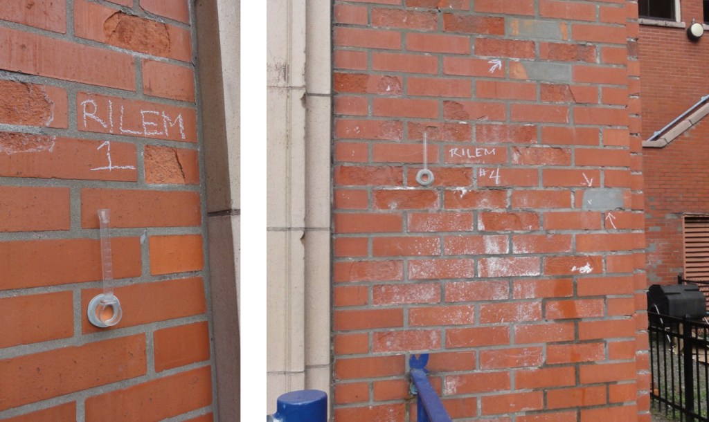
 Believing the white haze was a result of UV degradation of a masonry sealer, PMA conducted Reunion Internationale des Laboratoires D’essais et de Recherches sur les Materiaux et les Constructions (RILEM) tube tests of water absorption on the exterior brick on Duncan Dunn Hall. The area of brick chosen for the test was out of direct sunlight to avoid affecting the results and was conducted during dry weather. No movement of the water over a 45 minute period was recorded during the test. Masonry units, even those constructed with high quality clays under controlled firing conditions will absorb some water. The results of the field test on Duncan Dunn, along with the white surface haze, reinforced the assumption of the presence of a masonry coating.
Communication with WSU personnel and their internal research surmised that “the building may have had a sealer put on after the original construction. [WSU cannot verify the application through original records] but do know [that a sealer] was not used on a regular basis after [construction completion.] Back in the 70’s some “miracle sealer” of some sort was introduced on Campus and used at a few locations. Duncan Dunn Hall was among the buildings [receiving masonry sealers.] Today you can see the remnants of this as a white powdery surface that almost looks like efflorescence. [WSU] does not know the name of [the sealer] product.”
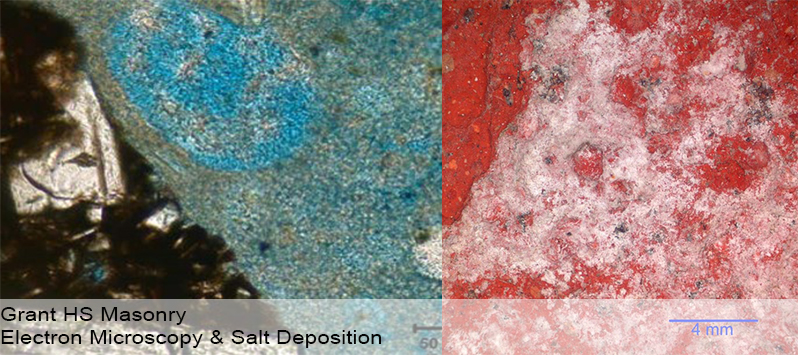
To confirm the presence of the sealer, PMA conducted lab testing via polarized light microscopy (PLM) episcopic microscopy, capillary fusion and Fourier-transform infrared spectroscopy (FTIR) per ASTM D1245 and E1252, respectively. FTIR indicated the material to be Poly(2-hydroxypropyl methacrylate), an initially water-miscible acrylic polymer that in these samples is at present very brittle and sloughs rather easily.Testing confirmed the presence of a “water-miscible acrylic polymer”. Due to chemical breakdown under UV, the chalky coating remaining on Duncan Dunn is no longer soluble in water.Because of the insoluble nature of the white haze, low pressure hot-water cleaning methods would not be successful. PMA recommended the Rotec Vortex cleaning system using a mirco-abrasive mixture of dolomite, water, and air. Ultimately this removal processes was successful with no damage to the masonry surface.
(1) Patent application for new formulation of sealers. (2) Types of Masonry Water Repellents, GSA web site. Information derived from ProSoCo Inc. product literature.
Written by Peter Meijer AIA, NCARB / Principal
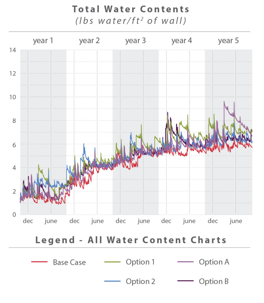 Total Water Content WUFI can predict the total accumulation of water over the time frame of the simulation, in this case five years. Over the course of each year a wall assembly will be wetted by the rain, and dry over the summer months. Differences in humidity and temperature between spaces may cause water condensation within the walls. If conditions do not allow condensation or other water to dry, materials may accumulate water over a period of time.
 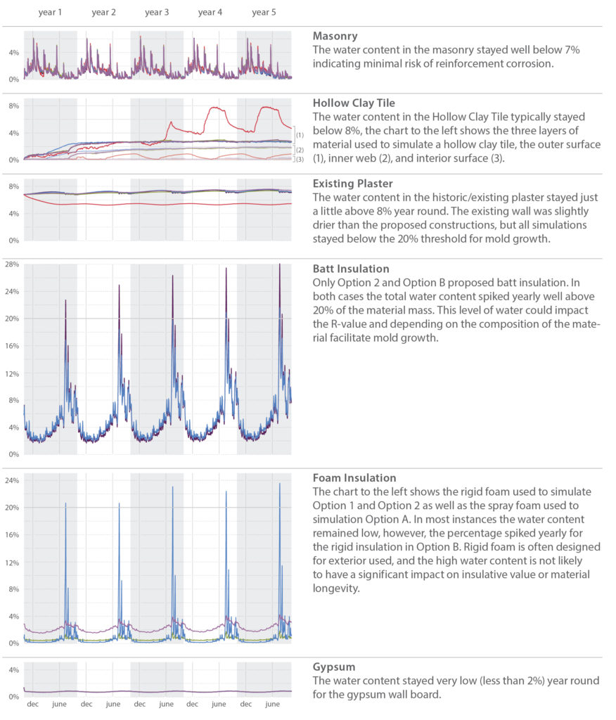 In general most layers remained well below the 20% threshold for mold growth. The insulation layers, however, are an exception. Options 2 and B both had batt and/or foam insulation which yearly exceeded 20% water. This quantity of water is somewhat concerning for the batt insulation as it may reduce the material’s R-Value and/or contribute to mold growth depending on the composition of the material. Solutions that used foam insulation performed better than those with batt insulation.
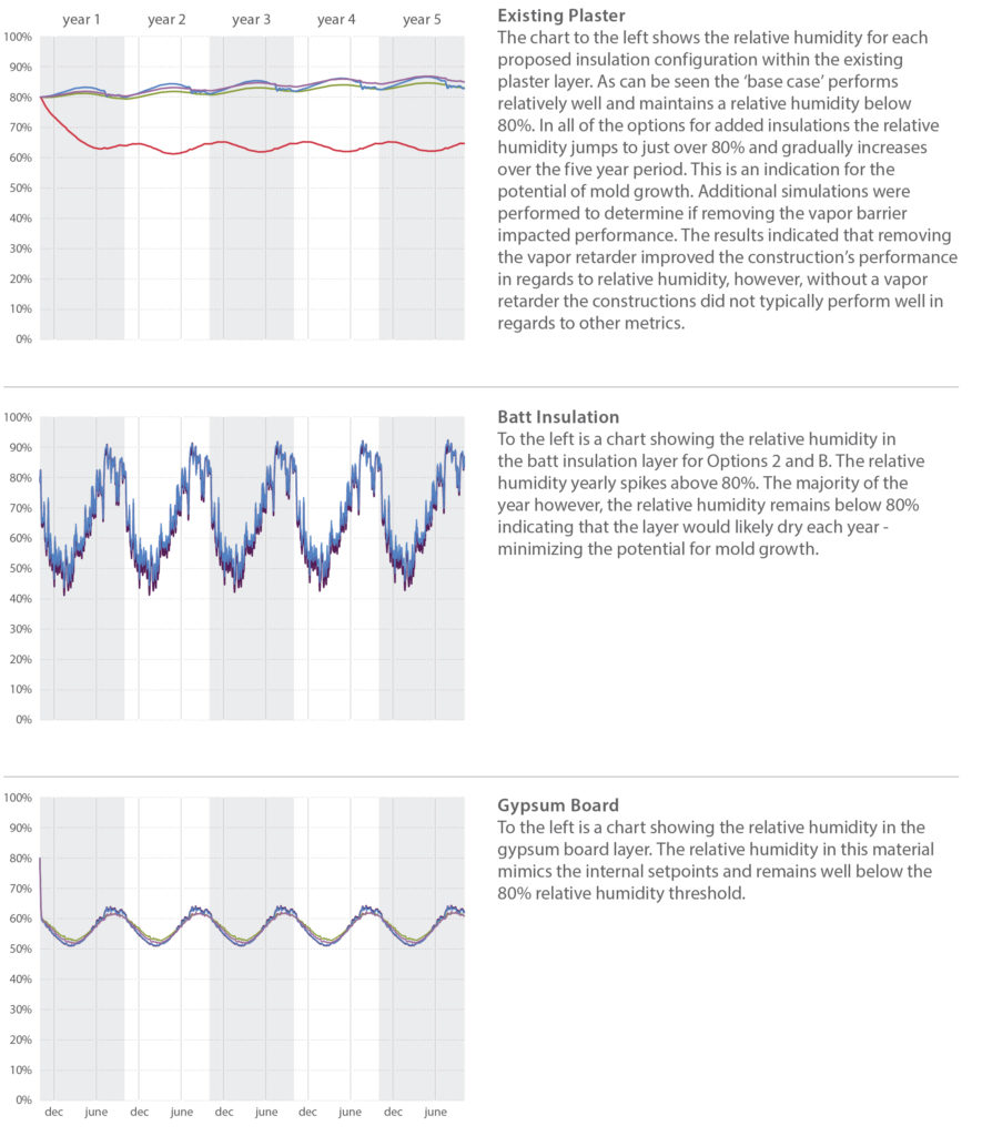
 20% Rehabilitation Tax Credit
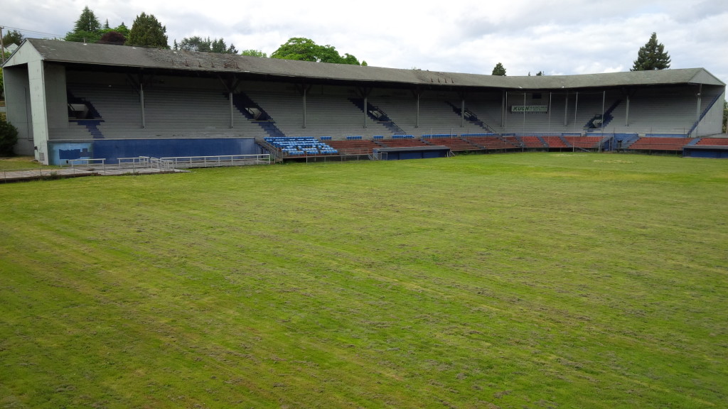
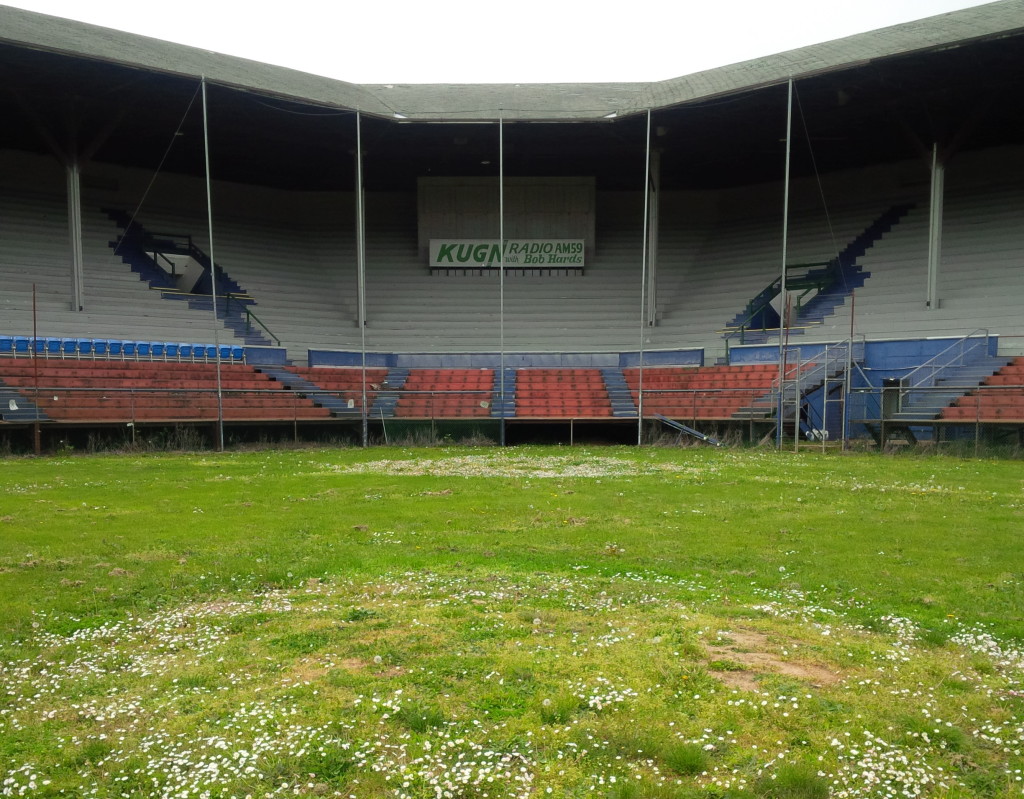 Since its creation in 1862, the ballpark has continued to have an influential impact on those who experience it. This impact is not only measured by heritage tourism to these sites, like Fenway Park or Wrigley Field, but also by how they are preserved. In some cases, such as Fenway Park, which is listed on the National Register of Historic Places, ballparks are preserved in a very traditional sense of the word. However, most ballparks never have the opportunity to reach the benchmarks needed to be preserved according to these preservation standards and are therefore preserved through a variety of alternative preservation methods. These methods, which span the spectrum from preserving a ballpark through the presentation of their original objects in a museum to the preservation of existing relics in their original location, such as Tiger Stadium’s center field flag pole, have given a large segment of our society an opportunity to continue their emotional discourse with this architectural form. Yet, the results of these preservation methods are commonly only the conclusion to a greater act of ceremony and community involvement that preludes them.
 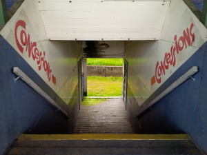 Part of this ceremony and community involvement is the simple act of participating in the ritual that is the game itself. Most often this is conducted through observation, as society, architecture, and sport become one for nine innings. However, other documented examples of ceremony and community involvement that express the level of compassion our society has for ballparks include ritualistic acts, such as the digging up and transferring of home plate. In some cases, this ritual has included the transferring of home plate via helicopter, limousines, or police escort. Ceremonies like this have also included, for better or worse, the salvaging of dirt, sod, and other relics from a ballpark to be, either cherished as a memento or repurposed in new stadiums. Nevertheless, these examples of ceremony only scratch the surface of the depth that is our society’s infatuation with sport and its architecture, more specifically the ballpark.
 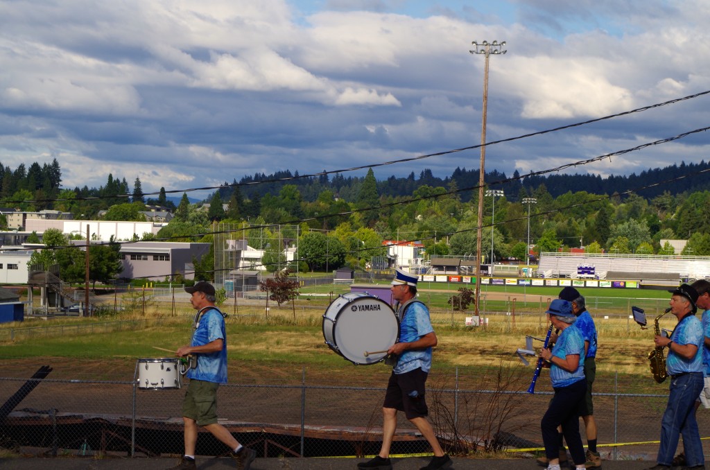 Ceremonial Acts & Community Involvement Efforts
 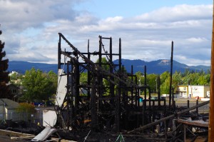 Led by the Friends of Civic Stadium president, Dennis Hebert, the organization held a wake in honor of their lost historic building. The wake, intimate in size, resembled a jazz funeral with a procession to the remains of the ballpark led by the One More Time Marching Band. Once at the site of the ballpark, there were multiple ritualistic acts that mimicked traditional funeral ceremonies. These acts included a moment of silence, a passionate speech by Dennis Hebert, and the always haunting rendition of Amazing Grace on bagpipes. After the ceremony, the Friends of Civic Stadium and the friends of Friends of Civic Stadium proceeded back to Tsunami Books where they continued to express their condolences and fond memories of the lost historic ballpark.