Since the creation of the ballpark in 1862 and the much later inception of the National Preservation Act of 1966, preservation and ballparks have not necessarily been synonymous with each other, especially when referring to those used for Major League Baseball. To further the point, of the 109 stadiums, ballparks, or fields used by Major League Baseball since 1876, only 43 exist today, and of those 43, only 9 are 50 years of age or older. This does not mean, however, that only 9 Major League Baseball stadiums have ever reached or even surpassed 50 years of age; it just means that meeting one of the most fundamental benchmarks in preservation does not guarantee survival. For that matter, neither does being listed on the National Register of Historic Places. Although preservation is practiced and taught through the lens of the National Park Service’s preservation standards, there are multiple factors that contribute to the preservation of a historic resource. Like anything, there is rarely, if ever, a single answer to solving a complex issue. This leaves the question, if not the existing preservation framework, what factors do contribute to the preservation of historic resources, specifically historic major league ballparks?
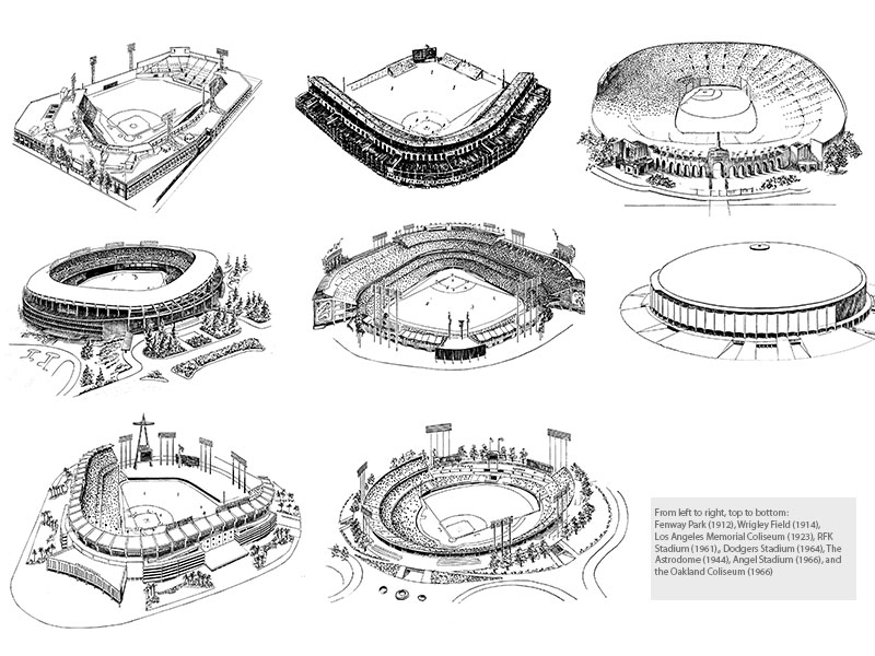
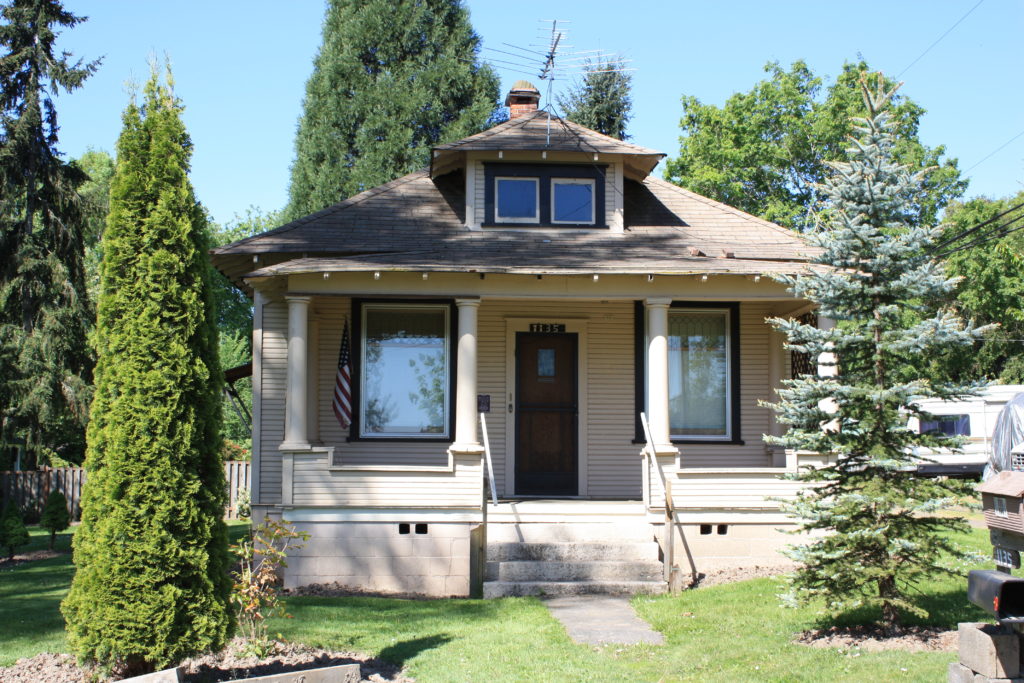
Though an intriguing question, it will not be completely answered in this observational study, given the number of variables for each resource. However, by analyzing the 9 existing Major League Baseball stadiums that have survived to reach the age of 50, Fenway Park (1912), Wrigley Field (1914), Los Angeles Memorial Coliseum (1923), RFK Stadium (1961), Hiram Bithorn Stadium (1962), Dodgers Stadium (1964), The Astrodome (1944), Angel Stadium (1966), and the Oakland Coliseum (1966), this study begins to quantify what factors have contributed to their prolonged survival and identifies two common elements: function and adaptability. This study also provides information that can be useful in steering and focusing preservation efforts toward the successful preservation of baseball stadiums, ballparks, and fields. Nevertheless, it should also be understood that, though the findings of this study identify patters of preservation, these patterns should not be used to determine historic significance or integrity.
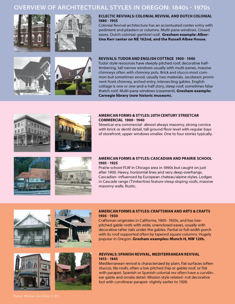
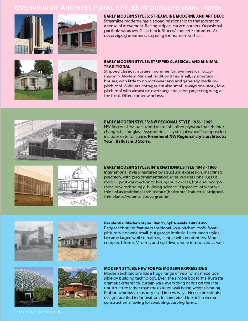
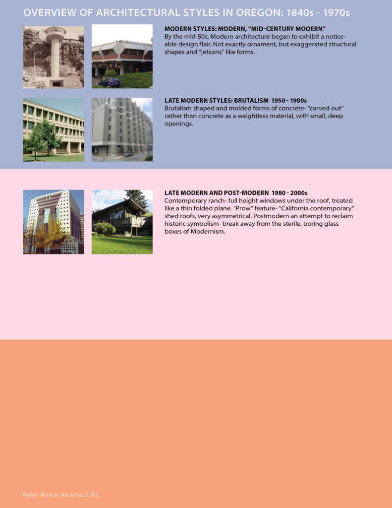
Elements of Survival
The first and most obvious element of survival for the 9 historic Major League Baseball stadiums is their function. No function, no purpose. Easily said and just as easily true. Of the 9 existing historic ballparks, 8 are currently being use by a Major League Baseball franchise or other sports program, as they were originally intended. The Astrodome is the only ballpark of the 9 that is currently vacant. With the exception of the Astrodome, which is pending rehabilitation, 8 out of 9 (88.9%) of all historic ballparks are functional. Whether through baseball, football, or soccer, keeping ballparks functional will not only contribute to their purpose for existence, but can keep them extant. In cases where Major League Baseball franchises or other sports programs build new stadiums, relocate, or disband, it is critical that the existing or remaining ballpark, stadium, or field finds a function, preferably one that utilizes its original design intent. Without it, its odds of demolition are significantly increased, regardless of its age, history, or cultural importance.
Ballpark Styles
Another common element of survival that these historic ballparks share is their ability to adapt to an evolving sport and culture through alterations. Though this use of alteration, in terms of renovation or rehabilitation, is a common standard within the National Park Service’s preservation rubric, ballparks are unlike other architectural forms because they are in a constant discourse with the sport of baseball, which has historically contributed to their continued evolution. Out of this relationship, four primary ballpark styles were created: The Pre-Classic (1871-1909), Classic (1909-1953), Modern (1953-1992), and Retro (1992–present). These styles, from the modest, wooden, Pre-Classic ballpark to the predominant, contemporary, Retro style ballpark, are equally representative of the sport and our society during their time of construction, thus contributing to their demolition when both evolved. Given this inherent fate, ballpark demolition is as common to the sport as superstition. So common, that an average of 16 ballparks have been demolished during each stylistic trend. However, those that have defied this characteristic have done so through their ability to mend both sport and cultural trend by adaptation.
Ballpark Alterations
After analyzing the histories of each of the 9 historic ballparks, 100% have undergone some form of alteration in pursuit of modernity. The most common alteration made was the addition or renovation of seating. The least common alterations made were the addition of kids’ play areas and the addition or renovation of dugouts. These statistics are expanded in the Historic Ballpark Alteration Chart. This chart shows past, undergoing, and projected alterations to each of the 9 historic ballparks observed in this study. Depending on age, these alterations, which include renovations and additions, may have been made to the same ballpark more than once.
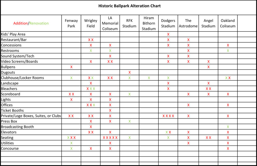
Overall, these alterations have unquestionably contributed to the extended lifespan of each of these ballparks. This has allowed 5 of them to obtain historic status, either nationally or locally, one of which used Federal Historic Preservation Tax Credits. More importantly, they all have retained their function and purpose, while not all alterations made to these ballparks align with the National Park Service’s preservation standards.
Titled “Preservation and Ballparks: A Survival Guide for the American Ballpark,” this study is meant to propel the discussion of the question: what factors contribute to the preservation of major league ballparks? Other factors that need further examination to truly understand the holistic approach to preserving ballparks are: 1) the financial impacts of preserving, redeveloping, or repurposing a ballpark; 2) the impact that a ballpark has on team success, franchise revenue, location and fan base; 3) and local preservation laws and ordinances for historic resources. Additionally, for further statistical analysis, this study would need a larger sample size, which includes historic minor league ballparks.
Overall, this study reinforces some of the most important and fundamentally crucial elements in preservation: function and adaptability. Though the findings made in this study are not new to the preservation field, the perspective of what elements contribute to preservation of a single utilitarian form, such as the ballpark, is. More importantly, this study also reinforces the necessity for change and growth for all structures, even if falling outside of national preservation standards. This does not mean that with change comes demolition, but that change should be embraced, as it has been for these 9 major league ballparks.
Written by Brandon J. Grilc, Preservation Specialist
Bibliography
Ballparks of Baseball. Dodgers Stadium. http://www.ballparksofbaseball.com/nl/DodgerStadium.htm.
Ballparks of Baseball. RFK Stadium. http://www.ballparksofbaseball.com/past/RFKStadium.htm.
Charleton, James H. Los Angeles Memorial Coliseum National Register of Historic Places Nomination Form. Washington D.C.: National Park Service, 1984.
Chicago Cubs. History. http://chicago.cubs.mlb.com/chc/ballpark/information/index.jsp?content=history.
Chicago Cubs. Construction Timeline. http://cubs.mlb.com/chc/restore-wrigley/updates/timeline/.
Cook, Murray. “Murray Cook’s Field & Ballpark Blog,” Hiram Bithorn Stadium Upgrades for 2010 (blog), May 26, 2010. http://groundskeeper.mlblogs.com/?s=hiram+bithorn+stadium.
Donovan, Leslie, Rachel Consolloy Nugent, Erika Tarlin, and Betsy Friedberg. Fenway Park National Register of Historic Places Nomination Form. Washington D.C.: National Park Service, 2012.
Georgatos Dennis. “Renovations Reshaping Oakland Coliseum.” http://www.apnewsarchive.com/1996/Renovations-Reshaping-Oakland-Coliseum/id-d9a080536647dd0a356dcbd51efd4095.
Grilc, Brandon J. “Stealing Home: How American Society Preserves Major League Baseball Stadiums, Ballparks, & Fields.” Thesis., University of Oregon, 2014.
Los Angeles Angels of Anaheim. Angel Stadium History. http://losangeles.angels.mlb.com/ana/ballpark/information/index.jsp?content=history.
Los Angeles Dodgers. Dodger Stadium History. http://losangeles.dodgers.mlb.com/la/ballpark/information/index.jsp?content=history.
Los Angeles Dodgers. Dodger Stadium Upgrades. http://losangeles.dodgers.mlb.com/la/ballpark/stadium_upgrades/.
Melendez, Sara T. Aponte. Hiram Bithorn Municipal Stadium National Register of Historic Places Nomination Form. Washington D.C.: National Park Service, 2013.
Powell, Ted. The Astrodome National Register of Historic Places Nomination Form. Washington D.C.: National Park Service, 2013.
Sillcox, Scott. Heritage Uniforms and Jerseys: A celebration of historic NFL, MLB, NHL, NCAA football and CFL uniforms and stadiums/ballparks/arenas. http://blog.heritagesportsart.com/
University of Southern California. The Coliseum Renovation. http://coliseumrenovation.com/overview.

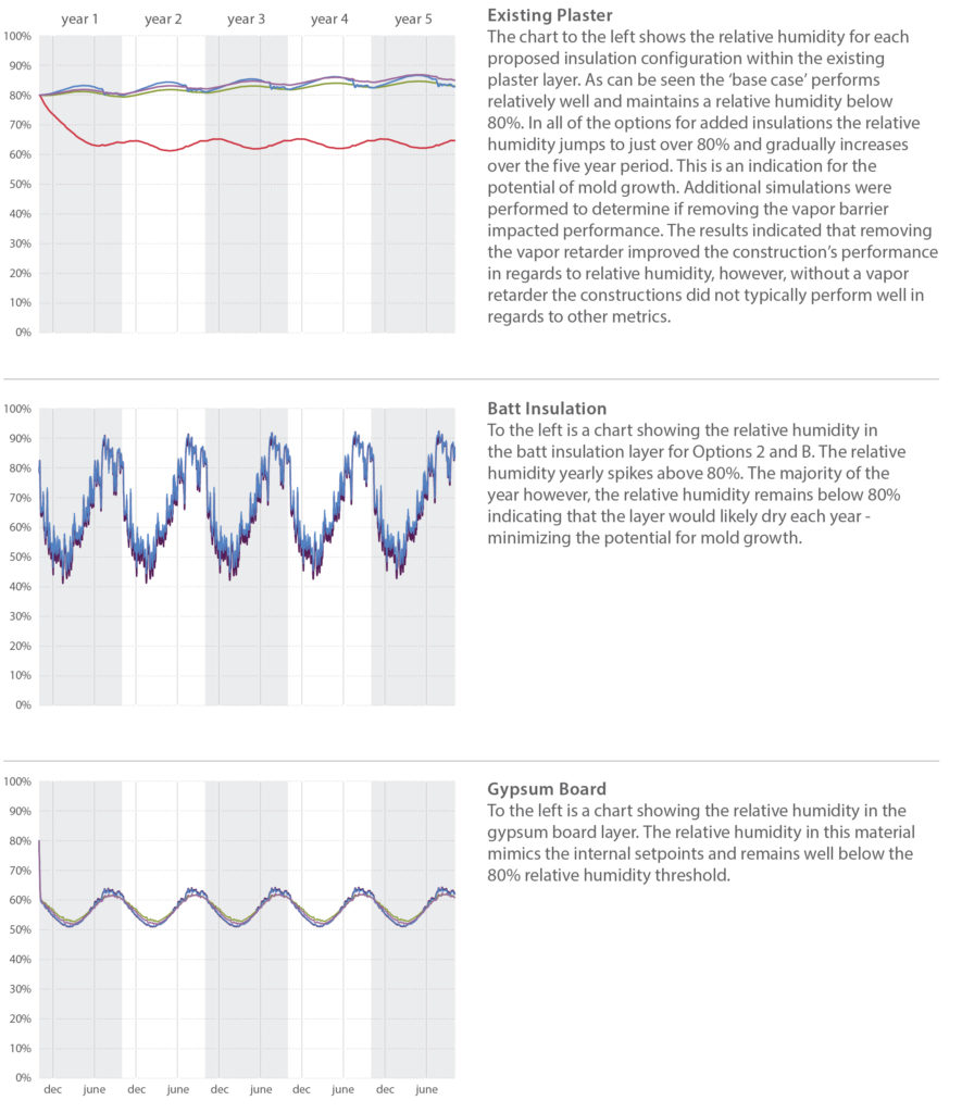
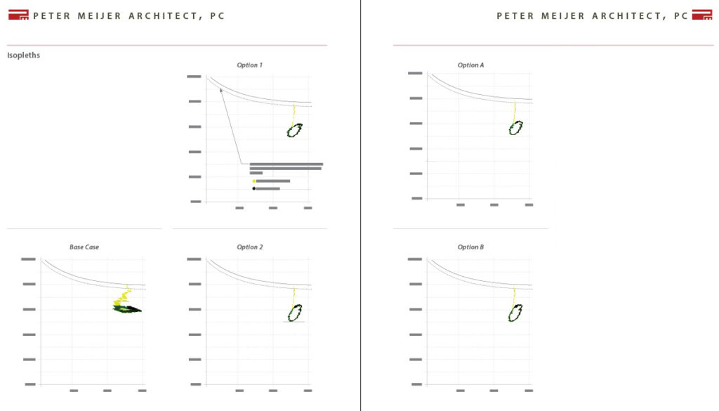
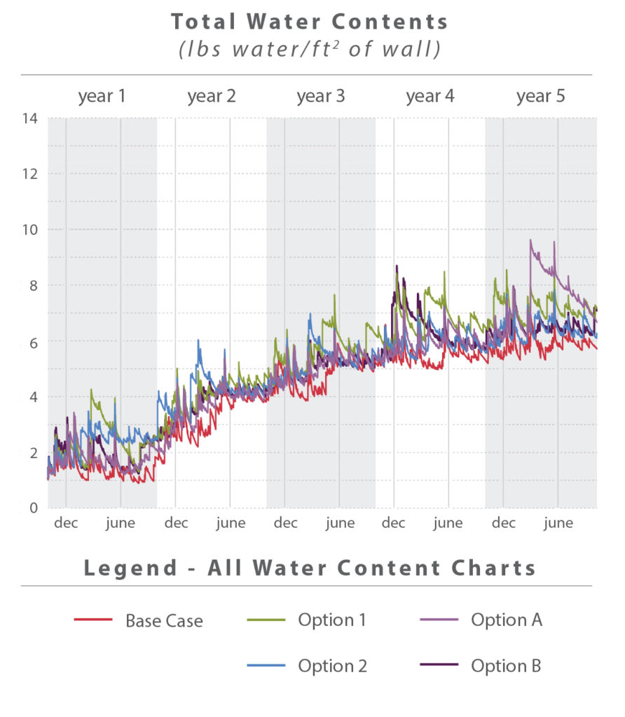 Total Water Content WUFI can predict the total accumulation of water over the time frame of the simulation, in this case five years. Over the course of each year a wall assembly will be wetted by the rain, and dry over the summer months. Differences in humidity and temperature between spaces may cause water condensation within the walls. If conditions do not allow condensation or other water to dry, materials may accumulate water over a period of time.
 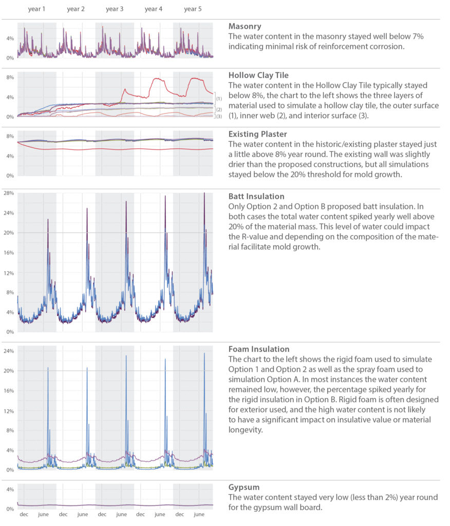 In general most layers remained well below the 20% threshold for mold growth. The insulation layers, however, are an exception. Options 2 and B both had batt and/or foam insulation which yearly exceeded 20% water. This quantity of water is somewhat concerning for the batt insulation as it may reduce the material’s R-Value and/or contribute to mold growth depending on the composition of the material. Solutions that used foam insulation performed better than those with batt insulation.