Tag Archives: historic

Using Revit for Historic Architecture

Revit is used widely for designing new architecture and for documentation of existing structures. When first looking at Revit one may assume that it is tailored for use with contemporary designs. The default ‘Families’ (the term Revit uses to describe all types of elements from furniture to windows, doors, annotation symbols, wall constructions, etc.) are all generic to new construction. Despite the pre-set generic components, Revit’s strength lies in the ability to create custom ‘Families’ and its capability of tracking both three dimensional design as well as linked information about components. When used correctly Revit can be a powerful tool for building assessment and historic renovation. At PMA we have found several tools in Revit that can help us accurately show historic elements, track information about conditions, show repair strategies, and graphically present data.
Revit-RecordingData
When working on historic structures it can be very important to accurately show existing elements. We often need to indicate exact pieces of terra cotta that require replacement or how a stone entry stair is configured so that the cost for replacement stones can be correctly estimated. We frequently create custom ‘Families’ to accurately show historic detailing. ‘Families’ of all types can be created to refine a model and add historic detail. Some of the common custom elements that we create include windows with historically accurate profiles, stacked walls that let us show terra cotta banding and differentiation in materials/wall thicknesses, complex historic roof structures, and custom patterns that match existing stonework. By adapting the generic Revit ‘Families’ and creating our own we are able to accurately represent historic features and structures.

Capabilities
One of Revit’s most useful capabilities is its ability to record and track information about building components. Unlike earlier drafting and 3D modeling applications, Revit can store information about material finishes, specification references, and much more! In Revit you can assign ‘Parameters’ to ‘Families’. ‘Parameters’ are used in a variety of different ways – but one of the most useful we’ve found is their ability to track the condition of specific building elements. For example, when we perform window surveys we can assign ‘Parameters’ to all of the modeled windows that describe the typical deficiencies observed. For each individual unit we can then record what deficiencies were discovered in the field. Once all of the information has been added to the Revit model you can create schedules in Revit to describe the condition of each window unit and total quantities. The information can be extracted from Revit and into spreadsheet software to analyze the data, present trends, and identify repair scopes for individual units.
Revit-Filters
Using Fliter’s
Revit’s ‘Filter’s’ function is another tool that we use in conjunction with ‘Parameters’ to better understand and present information that we’ve recorded in the field. Filters allow one to alter the graphics for components based on their ‘Parameter’ values. For example we commonly use ‘Filters’ to graphically show the condition of a building’s windows after a survey. We do this by creating a condition ‘Parameter’ where a value can be assigned to each window, for example, good, moderate, and poor. We can then use filters to highlight all of the windows in good condition green, those in moderate condition yellow, and those in poor condition red. Unlike a window schedule which may require some analysis – the color coded elevations Revit can create with ‘Filters’ are easy to understand and an excellent tool for presentations.

At PMA we have found Revit to be an invaluable tool that we use day to day for a variety of uses including 3D modeling, displaying point clouds, rendering, tracking information, and presenting data. Revit is a capable tool and with a little creativity one can tailor the application to complex historic projects. The ability to create complex custom ‘Families’ that track data about the structure make it possible for our office to efficiently record, analyze, and present date we observe in the field – bringing projects all the way through development, documentation of construction documents, and construction itself.

Review our ongoing building envelope project that utilizes Revit.

Revit-PresentingResults


Written By Halla Hoffer, Associate, Architect I

When Field Performance of Masonry Does Not Correlate with Lab Results

First presented at RCI 2015 Symposium on Building Envelope Technology, Nashville, TN

grant-hs-alterations-over-time

Background
When it was completed, Grant High School was typical of the high schools constructed by Portland Public Schools in the pre-World War II era. In addition to being an extensible school, including educational buildings constructed between 1923 and 1970, the school was also reflective of fire-proof construction through its use of a reinforced concrete structure with brick in-fill. (Portland Public Schools, Historic Building Assessment, Entrix, October 2009)

Over the last fifteen years, Portland Public Schools (PPS) noted an accelerated degree of masonry face spalling on the original 1923 main building and 1923 Old Gym particularly when adjacent to concentrated sources of surface water. Other areas of spalling were not as obvious including protected wall surfaces. The masonry spalling was not occurring on later additions including the north wing (circa 1925), south wing (circa 1927), and auditorium building (circa 1927). Upon closer visual examination, it was observed that individual units were failing in isolated protected areas of the wall surface. Failures in such areas could not be accounted for under direct correlation of heavy water intrusion and typical failure mechanisms.

The failure of the brick was potentially due to a number of separate or cumulative conditions including 1) excessive water uptake by the brick; 2) sub-fluorescence expansion of salts in the masonry, 3) freeze thaw; 4) low quality of the original 1923 brick; and 5) the application of surface sealers preventing water migrating to the exterior surface.

grant-hs-multi-surface-deficiencies

Field Investigation
In order to determine if the damage to the masonry was deeper than the surface, several wall-lets, an invasive exterior wall opening, were performed confirming the assembly of a multi-wythe masonry wall constructed in a typical fully bedded bond course with interlocking headers and no cavities between the first three brick courses. Hooked shaped, 3/32” gage, steel wire masonry ties in alternating courses and approximately twelve inches (12”) on center ties were found to be in good condition with no deterioration. The absence of corrosion on the in place brick wire ties indicated that little moisture was present inside the multi-wythe wall.

As a result of the hypothesis and field observations, it was prudent to conduct a series of lab tests to the brick, mortar, and patch materials to assist in the determination of 1) the quality of the brick; 2) the physical composition of the brick; 3) the quantity of naturally occurring compounds in the masonry and mortar, particularly salts in the masonry; and 4) the quality of the mortar. The findings would help narrow the potential cause of the spalling and lead to a more focused repair and maintenance process. Bricks were removed for testing of Initial Rate of Absorption (IRA – a test for susceptibility to water saturation) freeze thaw testing, and petrographic analysis, a way to determine the inherent properties of the clay and manufacturing process. Both pointing and bedding mortar samples, as well as, the previous patching material were removed and also tested. To rule out damage caused by maintenance procedures, faces of the brick material were sent to determine if sealants were used on the brick and, if present, determine the sealant chemical makeup. The presence of a surface coating may lead to retention of water within the brick and thus prevent natural capillary flow, natural drying, and water evaporation.

grant-hs-field-testing

Testing & Results
Samples sent to the lab for coating assessment were analyzed via episcopic light microscopy, and Fourier- Transform Infrared Spectroscopy (FTIR) per ASTM D1245 and ASTM E1252. The results found no hydrocarbon or organic formulations used on the surface of the brick refuting the hypothesis of a surface sealer.

Following modified ASTM standards, a 24-hr immersion and 5-hr boil absorption test on the brick were performed. The brick have a very low percent of total absorption at 9.5% for the 5-hr boil and 7.5% for the 24-hr test. The maximum saturation coefficient is 0.79 which is 0.01 over the maximum requirements for Severe Weathering bricks recommended for Portland climate (ASTM C216-07a Table 1). The Initial Rate of Absorption (IRA) is 5.7g/min/30in2 which equates to a very low suction brick or brick with low initial rates of absorption. The freeze thaw durability tests resulted in passing performance. All of these tests refuted the hypothesis that freezing temperatures were the cause of masonry spalling.

A brick material analysis was performed in general conformance with ASTM C856, ASTM C1324 (masonry mortar) and included petrographic analysis, chemical analyses, x-ray diffraction and thermogravimetric analysis. Samples were analyzed under a polarized light microscope for information such as materials ratio and presence or absence of different deterioration mechanisms. These tests were used to assess the overall quality of material, presence of inherent salts, excessive retempering, cracking, ettringite formation, and potential alkali‐silica reactivity.

grant-hs-electron-microscopy-salt-deposition

The Petrographic Characterization resulted in the most unusual findings and the most relevant results related to the observed failures. The polarized light microscope indicated carbonate based salt crystals seeping into the masonry from the mortar. No sulfate based salts, typically associated with the clays used for making brick, were present. Furthermore the inherent properties of the brick showed very small rounded voids and interconnected planer voids. Planner voids result from poor compaction during the raw clay extrusion process prior to firing.

Performance of brick in the field is a result of both material properties and resistance to micro-climates within the brick’s capillary void structure which cannot be repeated in the lab. Studies have shown a connection between small voids in the material property and susceptibility to longer water retention near the surface. With natural absorption properties, the brick is taking in a small quantity of water in very small pores. 24-hour immersion results are very low (7.5%). Publication of more in-depth studies correlates maximum saturation values for brick with low 24-hour immersion values. The effect of low immersion values and small quantities of absorbed water may increase the susceptibility in brick with small pore structure to freeze thaw failure.

The presence of salt migration out of the mortar and into the brick, plus small pore structure and low immersion values, combining with a cleavage plane resulting from manufacturing are contributing to the Grant High School brick spalls. Brick with smaller pores are less capable of absorbing the expansive forces of freezing water and drying salts. Interlaced pores creating linear plains parallel with the face of the brick create stress failure points resulting in surface spalling. Since the characteristics of the brick resulted from the firing and manufacturing process, the brick will remain susceptible to the failure mechanisms.

Conclusion
Field observations of masonry failures generally correspond with known failure mechanisms. However, it is not unusual that further analysis is necessary to confirm in-field performance and that typical laboratory test results are in conflict with in-situ performance.

The best corrective action is to minimize the amount of surface water and proper mortar joints and mortar composition. Additional spalls are likely to occur in the future due to the accumulation of expansive forces over a long period of time. Replacement of the spalled bricks is recommended over further patching. Leaving spalled brick in place will continue to worsen the condition over time and affect adjacent brick.

grant-hs-present-day


Written by Peter Meijer, AIA, NCARB, Principal

Assessing Union Station to be Part of Our Future

Portland’s Union Station is the only major railroad station built in Oregon, and one of the oldest major extant passenger terminals on the West Coast. From its inception, Union Station has functioned as a major transportation link to Portland and the west coast, with a continued vital role to play in future rail and multimodal transportation planning.
Union-Station-Historic-photo
A Sense of Place
Critical to adapting Union Station, and other historic structures, for current and future use is to thoroughly understand key elements and components that convey the sense of place and rich history of the structure. A deeper understanding enables informed decisions to be made about the potential of key characteristics to remain for future generations. Union Station was constructed between 1892 and 1894 and was designed by Van Brunt & Howe architects in the Queen Anne style with Romanesque detail. From 1927 thru 1930, the Main Concourse was modernized by Portland’s internationally known architect, Pietro Belluschi, to reflect the streamline era of rail technology. Like the original 1892 elements, the Belluschi modernization’s are equally important stories to tell.

Creating a graphic document annotating “changes over time” is an essential tool for evaluating how Union Station has adapted to improvements in rail technology, fluctuations in passenger volume, cultural shifts regarding train travel, as well as modifications to specific architectural elements that impact the historic integrity and interpretation of original design intent.
Union-Station-Report-Outline-pg2
Methodology for Assessment
Our method of developing the graphic drawing is to compare historic floor plans and historic photographs to current plans and images through a process of layering plans from different eras over one another and drawing the altered, or missing, elements (e.g. walls, furniture, spaces, etc.) in different colors. This methodology provides an easily interpreted floor plan. The use of color enhances the image and creates a visual record of both changes and original historic fabric. In reading the graphic drawing, it becomes readily discernible that changes include: wood floors replaced with concrete and new floors added; openings in the main concourse were moved and enlarged; the women’s waiting room and toilet were removed to widen the south hall, the stairs were renovated, and a new baggage counter was constructed. The covered concourse was glassed in and a section was made into the First Class Lounge, which remains today. And in the 1940s, a nursery, or crying, room was added.
Union-Station-PMAPDX-drawing
What is fascinating about the history of a building like Union Station, is that the rail lines and street patterns are also integrated with the function and use of the structure and have changed over time as well. The construction of Union Station came soon after Portland was fully connected by rail in 1883 to California, Montana, and rail lines running to the East Coast across the U.S. The Spokane-Portland-Seattle rail connection was finished in 1908. In 1922, Union Station became accessible to all major passenger railroads operating through Portland.

When originally constructed, six passenger car rail lines approached the rear of Union Station. The waiting platform consisted of planks on dirt with no canopy. The block across from Union Station consisted of a small restaurant, bar, other stores, and stables. A five foot iron fence bordered a large lawn and sidewalk to the south and west of the station. The High Shed, a large two-story metal shed was the first canopy built to cover the passenger platforms and extended perpendicular to the station. Under this High Shed, two smaller scale platform canopies were erected paralleling the tracks. A mail canopy was built at the north end of the building in 1915.

By 1920, the block across from Union Station’s main entrance had been converted to parking to relieve congestion. As automobile use increased throughout the city, parking configurations were constantly changing over the years. By 1923, an elevated walkway was built to connect the Broadway Bridge to the main entrance.
union-station-pmapdx-changes-overtime

With the introduction of larger diesel locomotives and potential for high speed rail along the northwest corridor, the track, platforms, and canopies have had to be modified. Safety and accessibility have also driven the need for changes and modernization. Documenting these alterations with graphics, provides a foundation from which to advocate for further refinement while recognizing historic precedent and protection of historic elements.

union-station-pmapdx-historic-photo

Written by Peter Meijer, AIA,NCARB, Principal

PMA is part of the DOWA-IBI Group team for this exciting PDC Union Station Renovation Project.

How to Improve Energy Efficiency in Historic Buildings

As historic architects we find window replacement projects to be particularly challenging — removing original materials from a structure can fundamentally change the design aesthetic. Our built environment must evolve to support more sustainable living, but finding the best way to achieve this goal for historic structures, while minimizing any aesthetic impacts, is an ongoing challenge.

When looking to improve energy performance the first inclination is often to replace the component with the lowest thermal resistance – the windows. Single pane historic windows provide minimal thermal resistance and contribute to heat loss through the building envelope. But is window replacement really the best option for reducing the carbon footprint of a historic building – how does it compare to other strategies?

energy-analysis-West Elevation
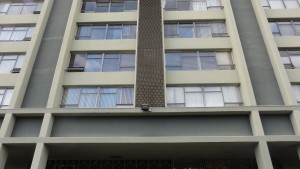
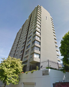
PMA recently performed an energy analysis study to answer that question. The project was to provide quantitative data on the energy savings associated with window replacement versus insulating exterior walls. We choose to study a structure on the brink of historic status – a 1960’s multi-story residential structure with large character defining view windows. The structure is composed of concrete walls, beams, floors, and columns with single pane aluminum windows. The existing building has approximately 36% glazing and no insulation.

The analysis we performed compared seven retrofit strategies ranging from minimal code compliance to super insulated walls and windows. Details on the specific constructions, r-values, and glazing properties are outlined below.

Construction Types Chart 
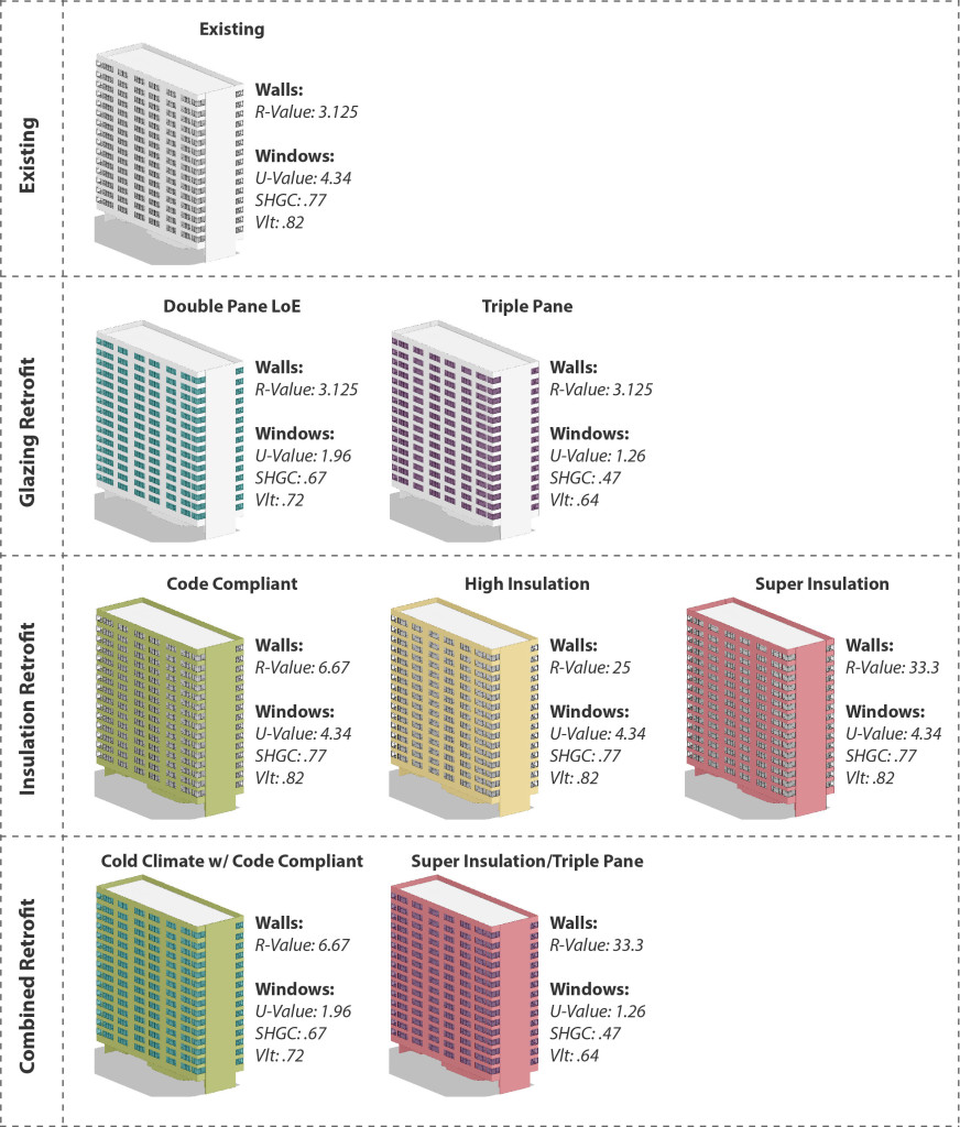
A wide range of constructions were chosen in order to see the full range of possible results. Future studies may focus on more refined material choices and a narrower set of parameters. The analysis was run in Autodesk Green Building Studio which is an excellent tool to perform basic energy models. While GBS does not allow for complex simulations it can quickly and accurately compare a variety of different design alternatives.

We chose to look at four different indicators to compare the results:
• Energy Use Intensity (EUI) indicates how much energy is used per square foot per year and is a very common way of comparing how different buildings perform.
• The quantity of electricity used per year indicates how much energy is used on cooling loads, heating loads, interior loads, and lights.
• The quantity of fuel used per year indicates primarily energy used for heating.
• The annual peak demand indicates the maximum amount of energy used at any single time over the course of a year.

We assessed the data in terms of percentage improvement over the Existing scenario. The charts below provide a comparison of the seven different retrofits.

Results Chart

The Results
What is intriguing in the results is the large difference in performance within the glazing retrofits options between the Double Pane LoE Glazing and the Triple Pane Glazing. While the Double Pane Glazing provides a notable improvement to the building’s energy performance it is still surpassed by all of the other retrofits. Conversely the Triple Pane Glazing far out performs all of the insulation retrofit strategies. The range between the two glazing retrofits indicates that new windows have the potential to have a substantial impact on energy performance. Unfortunately triple pane glazing is typically cost prohibitive and the LoE coatings applied to achieve maximum efficiency are incongruent with historic buildings. As technologies change and improve it is possible that these obstacles will be overcome – potentially making window replacement for energy efficiency purposes a more viable option.

window-detail
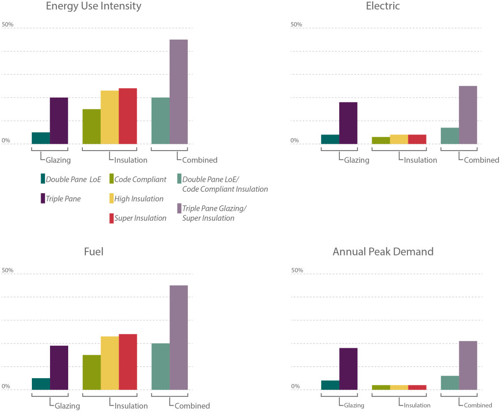
With current technologies the results indicate that adding insulation to a building has the most cost effective impact on energy performance. Installing new insulation is typically less expensive than window replacement and the results of this study show that Code Compliant (R-~7) insulation can have a significant impact on overall energy usage, outperforming Double Pane window replacement. Interestingly, the results also indicate that a High Insulation (R-25) retrofit performs better than a Combined Retrofit with Code Compliant Insulation (R-~7) and Double Pane Glass.

The results clearly indicate that adding insulation is an excellent way to improve energy performance without impacting the exterior façade of a historic building. Like any retrofit, insulation poses its own challenges: can it be installed on the interior without affecting historic finishes? Will changes in the temperature of the wall cause deterioration?, etc. Conversely, there are instances where window replacement is the right choice (when the existing windows have reached the end of their lifespan) and in this instance choosing a double pane glazing option can improve energy performance. In most cases, if you are looking to improve the energy performance of your building – it is more effective to explore insulation retrofit options rather than window replacement.

Written by Halla Hoffer, Architect I

The Challenge of Insulating Historic Buildings

A Limited Moisture Study

At its core, architecture in the Pacific Northwest is closely linked to moisture. The damp climate in Portland, Oregon has an impact on how we design new buildings as well as how we retrofit existing structures. Choices in construction, insulation, and flashing systems are always informed by our understanding of water. The success of any building envelope can be determined by how it performs against condensation, humidity, and water infiltration. Adding insulation to historic buildings is particularly challenging because the added material can change how a building envelope functions, leading to future moisture issues. At PMA we use WUFI to simulate and analyze how proposed retrofit strategies may impact the historic building envelope. For a recent project, we performed a limited moisture story of an unusual exterior brick wall that was to receive interior insulation. We studied how variations in insulative material and construction could impact the durability of both the brick and the interior wall structure.

The challenge when insulating a historic building is to protect the masonry from excessive moisture and cold. In uninsulated masonry walls, the building’s heating system warms and dries the masonry from the interior. If insulation is added, the masonry typically stays colder and wetter for longer periods of time, which can lead to deterioration. The intent of PMA’s study was to evaluate the masonry for future deterioration and to also identify any potential for condensation/moisture in the insulation cavity. WUFI was used throughout the design process to provide feedback on potential constructions and inform critical material decisions.

The building was built in 1921 and is unusual given that the original envelope consisted of a two wythe masonry wall with an interior plaster finish. A two wythe masonry wall is not common as it provides limited structure or protection from the elements. The renovation included an extensive seismic retrofit and the installation of new insulation to compensate for the existing wall’s limited structure. PMA was brought onboard to provide feedback on the building envelope detailing. We began our analysis by comparing the performance of the proposed envelope with that of the original building.
Constructions-Existing-building-envelope-pmapdx

Constructions-Proposed-building-envelope-pmapdx

As shown in the illustrations above the existing construction (small drawing) was: 8” of masonry on the exterior, an airgap where wood lath separated the masonry from the plaster, and approximately 1” of plaster on the interior. In comparison the proposed construction (large drawing) consisted of: the existing 8” of masonry on the exterior, a 1/2″ airspace, 1/2″ inch plywood sheathing, 6” of fiberglass batt insulation, a vapor retarder, and 5/8” gypsum with paint on the interior. The first step in our analysis was to accurately model each of these constructions in WUFI. Accurate material modeling is especially challenging in historic buildings. WUFI uses five different material properties to calculate moisture and heat movement. While an extensive built-in database exists for new materials, significantly less information is available for historic materials. PMA often tests materials to determine their properties and adds them to our expanding database of historic materials. The scope of this project didn’t allow for additional material testing. However, we ran several iterations of the analysis with different historic masonry materials to determine a baseline for our analysis. The remaining materials were chosen from WUFI’s building material’s database.

ProposedBrick-RelativeHumidity-pmapdx-wufi

ExistingBrick-RelativeHumidity 
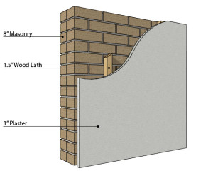
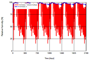
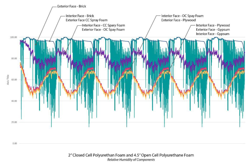
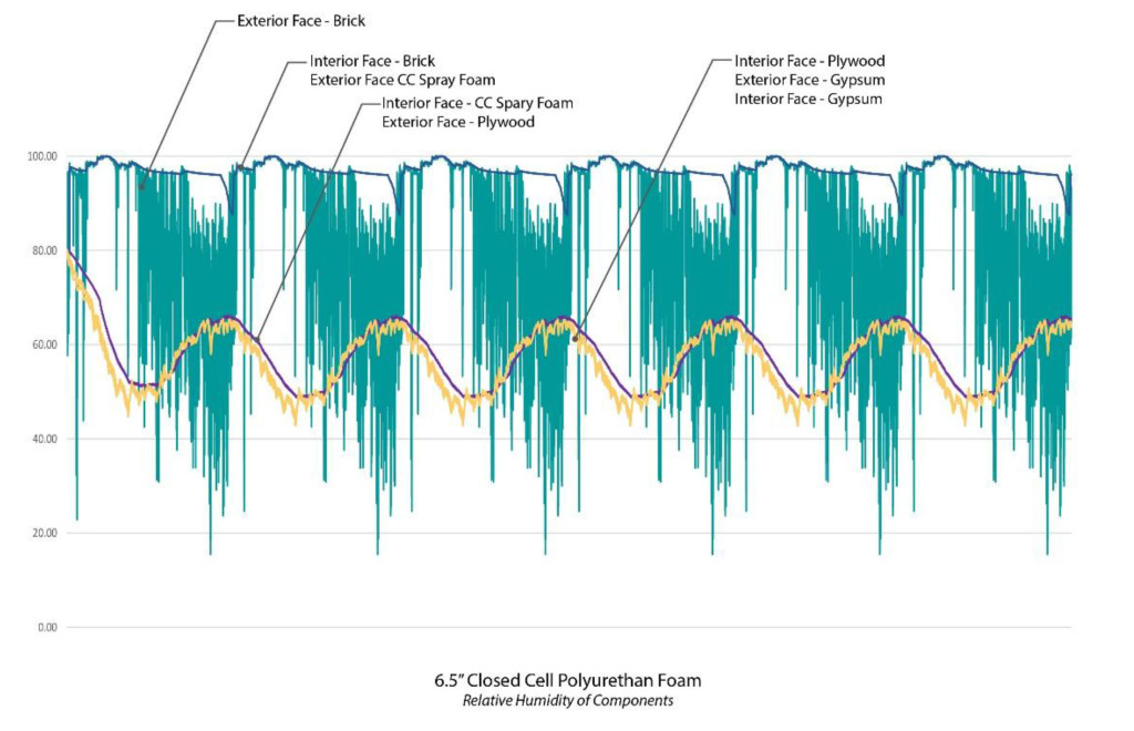
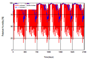
The results of the initial analysis indicated that as might be expected the masonry was not only exposed to longer periods of cool temperatures, it rarely was capable of fully drying. The two charts at the right show the relative humidity in the original construction and the proposed construction where each vertical line marks a calendar year. Note that a relative humidity above 95% indicates a likelihood of condensation. As can be seen in the original construction, during the wet months the relative humidity hovers at about 95%, but drops off significantly during the warmer months. Alternately in the proposed construction the relative humidity rarely drops below 95%, indicating that moisture is present in the masonry almost year round. When the individual layers are examined it becomes clear that in addition to considerable moisture in the masonry itself, water is likely to condense within the wall cavity. As seen in the series of charts below the relative humidity remains high through the airspace and plywood only dropping off between the exterior and interior face of the insulation.

ProposedLayers-RelativeHumidity-pmapdx-wufi
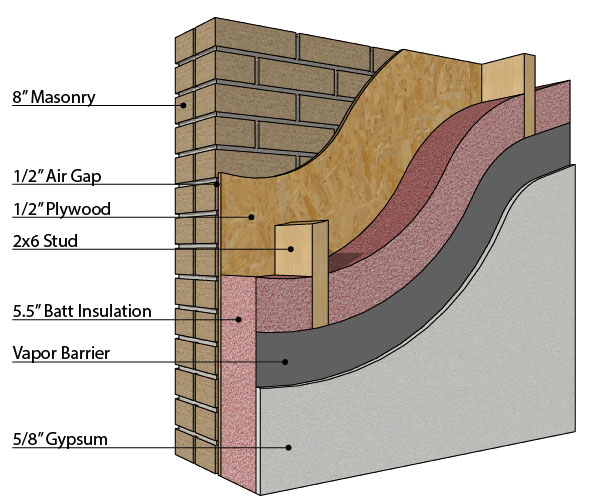
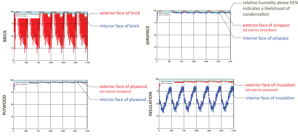
Given these initial results we suggested a redesign of the insulation system. The existing two wythe wall was not capable of adequately protecting the interior of the building, and the redesign had to accommodate for water infiltration through the masonry. Two options were discussed A) treat the masonry as a veneer wall and install waterproofing to the exterior face of the plywood as a drainage plane or B) install insulation that could be exposed to moisture and water. The constructability of Option A was significantly more complex than that of Option B so our initial analysis focused on Option B.

Constructions-ClosedCell-pmapdx-wufi

Constructions-Hybrid-pmapdx-wufi
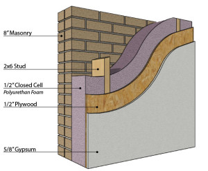
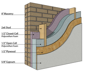
Spray foam was identified as an alternative to the original batt insulation because it can both serve as a vapor retarder and insulate even when exposed to moisture. Two design options were investigated to determine the extent of closed cell foam necessary to adequately protect the interior surfaces from moisture. As can be seen to the right we investigated a construction filled entirely with closed cell polyurethane foam vs. a cavity filled with a combination of closed and open cell polyurethanes. Additionally we looked at the condition of moisture/heat transfer at the perceived weakest point in the structure, where the structural framing was only barely (1/2”) separated from the masonry. The structural integrity of the seismic upgrade depended on a minimal distance between the framing and the existing masonry, but concerns existed as to whether the wood would be exposed to enough moisture to cause mold.

At the conclusion of the study the spray-foam hybrid option was chosen for further detailing and construction. The combination of closed and open cell foams effectively protected the interior from moisture and condensation. In each renovation scenario studied the exterior masonry was exposed to similar conditions; including increased moisture and cooler temperatures. Given every strategy resulted in similar conditions it was the combined performance of the hybrid system that stood out to the design team.

When the assembly is studied at the structural members, the interior components (plywood and gypsum) retain their low relative humidity. It is important to note that in this scenario the exterior face of the structural wood members are at above 80% relative humidity year round. These conditions may facilitate the growth of mold according to ASHRAE 160-2009. It is recommended that moisture protection be applied to the outer potion of these members.

When the assembly is studied at the structural members, the interior components (plywood and gypsum) retain their low relative humidity. It is important to note that in this scenario the exterior face of the structural wood members are at above 80% relative humidity year round. These conditions may facilitate the growth of mold according to ASHRAE 160-2009. It is recommended that moisture protection be applied to the outer potion of these members.

This chart shows the hybrid option of using both open and closed cell polyurethane foam to insulate and weatherproof the building. The relative humidity remains high at the exterior components, but is reduced to well below 80% on the interior components.

This chart shows the hybrid option of using both open and closed cell polyurethane foam to insulate and weatherproof the building. The relative humidity remains high at the exterior components, but is reduced to well below 80% on the interior components.

When only closed cell polyurethane is used to fill the cavity the performance is similar to the hybrid scenario. This chart shows that the outer components are constantly at a high relative humidity while the interior components remain more closely linked with the interior conditions of the building.

When only closed cell polyurethane is used to fill the cavity the performance is similar to the hybrid scenario. This chart shows that the outer components are constantly at a high relative humidity while the interior components remain more closely linked with the interior conditions of the building.

Ultimately, the project serves to show how an iterative approach to designing building envelope retrofits is critical to achieving an effective solution. By carefully modeling and simulating the initial proposed system we were able to provide critical feedback that led to a more effective and responsive design. In this case, fully understanding the unique two wythe wall system was essential to providing adequate moisture protection for the wall cavity. While a typical masonry wall is capable of preventing water intrusion, the minimal depth of this masonry wall proved insufficient. Our analysis uncovered this flaw and allowed the system to be redesigned to work more effectively. Unlike new construction where the entire envelope system is designed simultaneously, with historic buildings we must work backwards from the existing to create a cohesive design that responds to and compliments the original elements. WUFI serves as an essential tool in understanding the existing and investigating the new.

Written by Halla Hoffer, AIA / Associate

Steps to Replacing Historic Wood Windows

QAHSC-landmarks-review-pmapdx
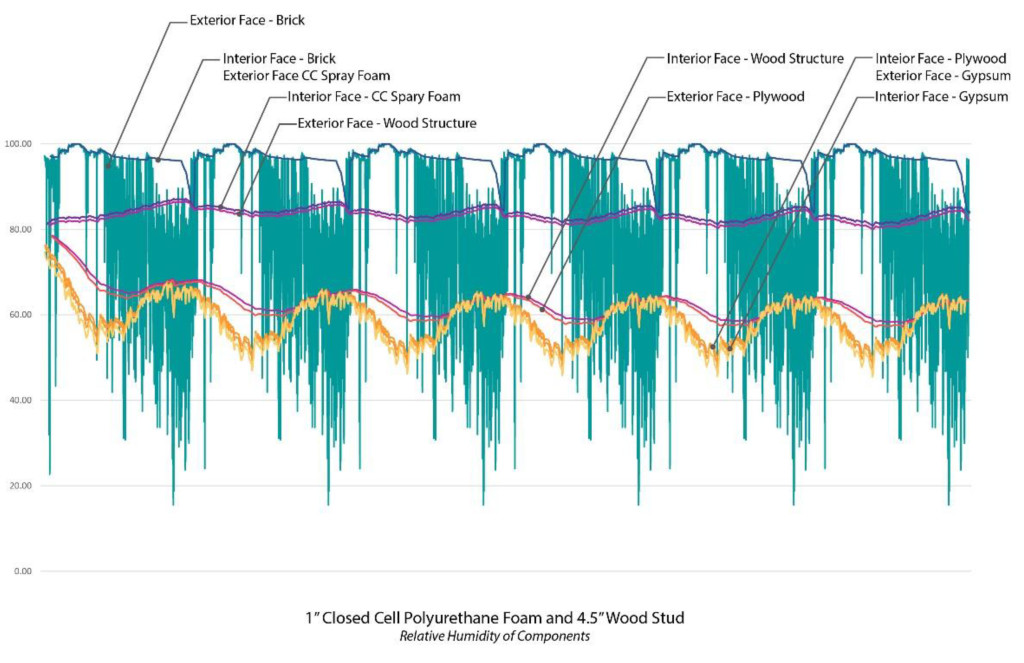
Our first choice, and ethical preference, is to retain historic wood windows. Repaired and maintained wood windows constructed of old growth lumber will outlast any modern alternative. We advocate strongly for a process and philosophy that seriously evaluates retaining original material. The best approach compares long-term costs, embodied energy, and cultural importance relative to the same criteria for new replacement material.

But what do you do when the comparative process favors new material and replacement becomes the option of choice? And how do you gain jurisdictional and historic approval for removing character defining features from a historic property? Correct research, documentation, presentation, and material selection are the key factors to successfully replace historic wood windows.

Lack of maintenance is rarely accepted as a justifiable rationale for window replacement. Arguments for window replacement based on peeling paint, surface tracking of the wood, and/or glazing putty failure are typically countered with comments that benign neglect is a conscious act and straight forward maintenance will reverse the deterioration and deficiencies noted. A better strategy is to base replacement rational on existing significant deficiencies that require financial investment and resource allocation to repair the deficiencies.

QAHSC-landmarks-review-windows-pmapdxMost existing, older properties have had more than one owner. Research into original design documents, major rehabilitation projects, building permit requests, and other documents provide insight into processes that might have replaced original material. The removal and replacement of non-original material is justifiable and acceptable rationale.

Documentation by means of an on-site, window by window survey is the only method that will yield quantifiable data regarding the physical condition of existing wood windows. The resulting comparative data is critical for structuring an argument in favor of replacement. The field observations also provide invaluable information pertaining to the means and methods of construction and conversely deconstructing, or removing, the windows. Understanding wood window construction is important to understanding how wood window fail. Source documents like the Association of Preservation Technology’s Window Rehabilitation Guide for Historic Buildings (1997) and the National Park Service Preservation Briefs: 9, The Repair of Historic Wooden Windows provide exploded diagrams of both wood window construction and typical failure locations. These locations generally include the sash mortise and tenon joints, the exterior stops, and horizontal rails. The field assessment will need to document the quantity, location, and extent of any failed components.

QAHSC-landmarks-review-pmapdxAfter a thorough evaluation and understanding of the existing wood windows, the next decision is to choose a replacement product. In-kind replacement,(i.e. wood window for wood window; true divided lites for true divided lites, matching pane divisions, etc.) is preferred. When the replacement window is virtually identical to the historic window, it is hard to say no. Absent exact replacement, the visual qualities exhibited by the cross section profiles, the sash height and width, and the proportion of wood to glazing, are the most important attributes to match. Appearance from the exterior will trump appearance from the interior during a historic review approval process.

How the research findings, existing conditions, and replacement products are presented is fundamental to a successful request to replace historic wood windows. Agencies and commissions with jurisdictional review and approval authority require clear, methodical, and linear processes to understand the research, findings, and selection process. Collating the field data using charts and graphs, including graphic representation of previously altered windows, and defining the quantity of failed components will assist a decision in favor or replacement.

QAHSC-window-flashing-pmapdxWhen an opportunity to retain original fabric/windows is available, the opportunity should be incorporated into the work. Even retaining as little as 20% of historic fabric will increase the likelihood of approval for replacement of the remaining components. The retention of historic fabric also allows successive generations to better understand the history and changes of an existing property.

Written by Peter Meijer AIA, NCARB, Principal.

Inherent Sustainability of Historic Architecture

Trinty-Episcopal-Church-pmapdx

The terms ‘Sustainability’, ‘Green Building’, ‘Environmental Design’, and other similar phrases have recently become critical in how we approach and understand contemporary architecture. As concerns over pollution, global warming, and our impact on the surrounding environment have gained traction – we have begun to understand the building industry’s contribution to these issues. The US Green Building Council reports that buildings account for 39% of all carbon emissions in the United States, surpassing both industry and transportation.

At the core of the issue is how architects, clients, and the public imagine buildings should function and operate; a vision which has transformed over the last two centuries as technological advances have developed the capabilities of the building industry. In the last two centuries, buildings have become monuments to the Industrial and Technological Revolutions. The development of electrification, central heating, air conditioning, steel and concrete have transformed how architects design and how users function within the built environment. This shift has transformed architecture from an inherently sustainable practice into a much more complex and often unresponsive process.

While the phrase ‘sustainability’ has only recently been associated with architecture, many historic buildings were designed by incorporating sustainable practices. Without electricity, buildings by necessity had to respond to site orientation and the local climate. Natural ventilation was used to passively cool buildings, well placed windows provided natural light, and construction methods varied by location to provide an appropriate level of protection from the surrounding environment. However, as a result of modern renovations, these sustainable attributes are not always utilized to their fullest potential.

Historically, large, operable windows were an integral component of architecture in moderate climates like the Pacific Northwest. The glazing provided natural daylight while the operability allowed users to ventilate spaces based on thermal comfort. Today, the operability of windows in many historic buildings has been compromised for a variety of reasons:

• Windows that have been fixed shut to prevent users from overriding the central air system.
• Broken window hardware that hasn’t been properly maintained.
• Windows that have been painted shut.
• Windows that have been fixed shut to minimize maintenance.

Without the natural ventilation that was incorporated into the original design, these historic structures often overheat and/or rely heavily on central air conditioning. One must question why the inherent sustainability of these historic structures was compromised. Was it simply our initial infatuation with mechanical heating/cooling systems? As passive sustainable design gains traction it is critical that we understand the capabilities of historic structures in regards to their inherent sustainability.

For further investigation we have identified a case study that explores the possible impact reintegrating natural ventilation may have on thermal comfort. Trinity Episcopal Cathedral in Portland, Oregon was built in 1906 and the original design included 10 operable dormers along the Sanctuary roof. The dormers have since been boarded over, preventing rising heat from escaping. Congregants find the space overheated during the summer months and one must question whether operable dormers would provide adequate ventilation to sufficiently cool the space.

An energy model has been developed using OpenStudio and EnergyPlus to compare the thermal comfort of occupants within the space. A baseline model mimics the existing conditions and provides a comparison for the two different natural ventilation configurations. One natural ventilation configuration re-introduces the operable roof dormers to vent hot rising air. The other natural ventilation configuration re-introduces the operable roof dormers and integrates additional ventilation at the exterior wall of the building to produce stack ventilation.
Trinity Results-wufi-pmapdx

While the project is still in process, initial results indicate that natural ventilation could have a significant impact on the space. The study has focused on the thermal comfort within the Sanctuary and results show that natural ventilation could dramatically lower indoor temperatures during peak summer months.

Trinity Results-wufi-pmapdx

Trinity Results-wufi-pmapdx

The results continue to be fine-tuned, and further refinement of the energy model will include:

• Adjusting schedules/systems to more closely reflect the building’s occupancy.
• More accurately defining the exterior infiltration rates.
• Exploring more relevant solutions for integrating stack ventilation that don’t require the large operable exterior windows. For example integrating ventilation through the basement into the main sanctuary.

While further research remains to be done, initial results are promising and demonstrate the inherent sustainability of the structure. While each building is unique, this Case Study shows how reintegration of natural ventilation may be a viable solution for passive cooling in uncomfortably warm historic buildings. Continue to check back for updates as we refine our study and explore how re-integration of natural ventilation may result in energy savings!

Written by Halla Hoffer, Architect I

The Evolution of Open Space

Photo by Charles Birnbaum courtesy The Cultural Landscape Foundation.

Photo by Charles Birnbaum courtesy The Cultural Landscape Foundation.

Public open spaces, especially urban open spaces, are coming into their own recognition as historic resources. They are receiving more attention because well-designed outdoor landscapes reflect our values as individuals and as a society. Though the way we use these spaces may shift over time, the designs still reveal our collective aspirations for our relationships with nature, the built environment, and with each other.

Two parkscapes in Portland are particularly good at showing us the values and aspirations of their era, and it is worth remembering the design concepts, and remembering how our interaction with the parkscapes has changed over time. These landscapes are the Washington Park Reservoirs, completed in 1894; and the SW Portland sequence of places anchored by Keller** and Lovejoy Fountains, completed in 1966-70.

historic-WPR-pmapdx
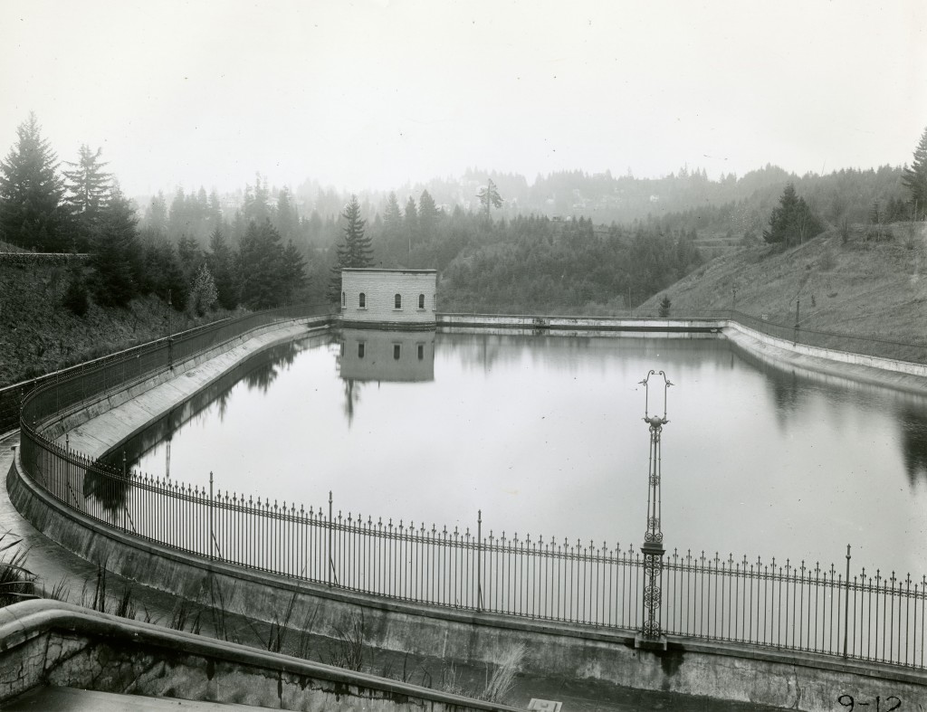
Washington Park Reservoirs is a historic district listed on the National Register of Historic Places. It was developed to store and distribute clean drinking water, but it had another important function which drove its design: it was a recreational destination for a growing urban population. At the end of the 19th Century, the City Beautiful movement across American cities inspired planners and politicians to create parks as refuges from urban life. Parks were seen as restorative, where citizens could breathe fresh air, stroll along paths or promenades, and view natural plants, lakes, and garden vistas. Many of our most famous American parks were developed during the City Beautiful era, including Central Park in New York City.

Washington Park and the Reservoirs were directly served by public transportation (the Portland cable car) and offered panoramic views east over the City towards the Cascade Mountains. The Reservoirs served as reflective focal points in a landscape designed to look completely natural, yet evoke romantic memories of western European aqueducts and fortresses.

By the 1930s, civic open spaces and the development of public parks had become unaffordable for most municipalities, and also had become less valued by Americans who were increasingly moving out of the cities and into suburban developments. Existing parks were generally not well maintained, and crime and vandalism created more abandonment by well-off city dwellers. By Mid-century, though, a new type of open space was being developed in many American cities. Under urban renewal programs, cities razed perceived decrepit, crowded, and crime-ridden neighborhoods and replaced them with open, clear, utopian style developments.

Portland Open Space courtesy TCLF

Portland Open Space courtesy TCLF

One of the largest and most successful Modern-era urban renewal projects in Oregon includes a series of public parks, walkways, fountains, and plazas designed by landscape architect Lawrence Halprin, known as the Halprin Open Space Sequence. The project, at the south end of downtown Portland, was listed on the National Register of Historic Places in 2013. The Halprin nomination quotes from J. William Thompson, editor of Landscape Architecture magazine, comparing Frederick Law Olmsted Sr. (the progenitor of the City Beautiful movement) to Lawrence Halprin: “For Olmsted, the vision was one of pastoral relief from smoke and crowding; for Halprin, one of celebration of the city’s rambunctious vitality. Both viewed city parks and open spaces as a meeting ground for people of all classes.”

How much has our use of these two open spaces changed over time? We still get out of the house to walk in a park, possibly more than we did 50 years ago or 120 years ago. We have more leisure time, many of us own pets that need exercise, and people stay active longer than they used to. There have been societal changes that work against the popularity of local parks, including the ease of automobile transportation (pulling people further afield), the proliferation of other ways we can spend our leisure time, and the rise in obesity; but in general we use and care for our shared local parks and open spaces. However, there are changes in our relationships with these two specific open spaces that illuminate deeper trends in our society. One of the most complex relationship is the trend towards an increased mistrust of government.

WA Park Reservoirs 130329 011
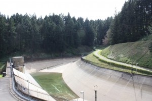
The Washington Park Reservoir area shows the most profound shift in use over time. The need to cover and further protect drinking water in underground storage contains in lieu of open Reservoirs reflects a growing national divide between government and the public made visible by current limited access to a once prominent bucolic public destination. Perhaps a certain level of distrust is to be expected from decisions affecting public safety, but the potential loss of the Reservoirs as a contemplative, experiential destination is in stark contrast to the one of original design intent. Part of the current limited access results from the explosion in liability, where government agencies can and will be found at fault for any harm that might befall a park user or a water consumer. Federal regulations requiring municipal drinking water to be covered also feed our collective sense that there are malicious people among us.

The City of Portland is boldly attempting to both comply with the federal ruling to cover our drinking water reservoirs and restore the original city beautiful interaction with the park. In so doing, the City will eliminate the biggest concern with the liability and safety of our drinking water and the restorative design will re-imagine the Reservoirs, not as a highly urban, interactive series of features like the Halprin Sequence, but as a tranquil, even romantic, natural setting for the public to once again walk through and enjoy a natural beautiful city.

Lovejoy-Pavillion-preservation-pmapdx
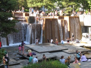
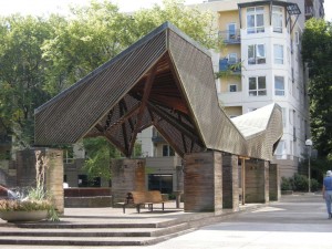
Amazingly, the Halprin Open Space Sequence continues to survive the “age of liability” with its wonderful interactive fountains, plazas, and pools intact. Nothing this fun- and potentially hazardous- will likely be constructed again as a public project. The design reminds us that we must be responsible for protecting this level of freedom, and that this very public- and yes, democratic- open space, is uniquely valuable as a symbol of public trust.

Written by Kristen Minor, Preservation Planner

Towards a Death of Architecture

Buildings are physical representations of the social, economic, political, technological, and cultural climates of their eras of origin. Ultimately buildings represent our cultural heritage and our architectural history. However, mid-century modern era buildings are increasingly interpreted as antiquated architecture that is functionally obsolete and lacking use in today’s society. Our recent-past modern buildings are being labeled as “failed” or “useless” architecture. As a result, mid-century modern architecture is rapidly being demolished and replaced with newer sustainable structures believed to better represent our most current social and cultural ideals. Current architecture is believed to be far more aesthetically pleasing than their modern predecessors.
But in the context of society, including heritage, what constitutes “useful” architecture verses useless building? There must be a relationship of parts to complete the building, but structure and function alone do not equate to architecture. Perhaps “useful” should be a term connected to architecture exhibiting enduring design excellence? Paradoxically, design excellence is tangled with style, and history demonstrates that style preference is ephemeral, subjective, and fluxuates at a high velocity. Yet the loss of style preference, or the falling out of design aesthetics favor, is one of the biggest rationale for the demolition of modern era buildings. Presently, Brutalism is at the crux of the demolition/ preservation debate.

Framed in the context of history, it can only follow that Brutalist buildings were going to be executed as formal monumental concrete structures that directly juxtapose (even challenge) their environments. But more often than not, the perspective of historic context is outnumbered by present aesthetic preference. For example, Prentice Women’s Hospital (Bertrand Goldberg) in Chicago, the Berkeley Art Museum (Mario Ciampi) in California, and several of Paul Rudolph’s brute beauties were technological and architectural triumphs of their time. However, the Brutalist buildings like other modern era buildings that rate low on the aesthetic-scale have been equally disregarded in their maintenance. The argument for demolition based on deficiencies caused by a lack of maintenance becomes all too convenient. The wide-spread demise of brutalist civic and urban buildings is a demise of the ideologies
behind the intent of the architecture and those housed within.

Aesthetics cannot be the pretext for significance or the preservation of architecture. Letting aesthetics judge value will strip our architectural history of some of the most influential and innovated examples of modern era architecture. In effect, we are killing, and ultimately denying claim to, a portion of our architectural history. There is value in the perspective of context and value in re-using and re-imagining modern era architecture. If aesthetic preference continues to get in the way, what use is there for the architect or an architectural legacy?

Written by Kate Kearney, Marketing Coordinator

When A Master Work Fails: Three Case Studies

Some of the greatest restoration challenges arise when historically significant works weather, degrade, are neglected, or simply have suffered through inappropriate renovations. Restoration strategies are compounded when original historic materials, either natural materials like wood or stone, or production processes are no longer available. And when the failure is due to improper design or inadequate construction methods, corrective restoration methods may alter or compromise the original design intent. The following three case studies illustrate restoration philosophies based on balancing preservation, resolving the underlying building deficiencies, and introducing “thoughtful change” in protecting significant local structures for future generations.
John Yeon 2012 004
Case Study 1
John Yeon’s 1948 Portland Visitors Centerwas designed as an exhibition showroom with large open spaces, a pinwheel plan, on a highway dividing median, accessible by car, and constructed of standardized wood framing components including recently developed experimental plywood. When the highway was replaced with a riverfront park and the Visitor Center programming was relocated, the singular purpose building became obsolete resulting in a number of incompatible conversions including substantial alteration of the main gallery space to an industrial kitchen. Contributing to the slow demise was the degradation of the exterior wood components and failure of the plywood as a result of the northwest climate and inadequate weather protection. By the time the Friends of John Yeon and the City of Portland Water Bureau invested resources into the restoration, the Visitor Center had lost or compromised 80% of its historic interior finishes and the exterior façade had been heavily altered. However, the original floor plan, massing, scale, exterior spaces, and essence of Yeon’s modular design and sense of place remained.
WS Scheme 3 Entrance 101209
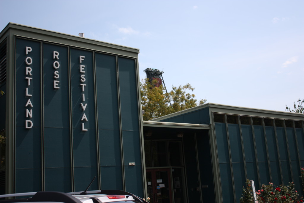
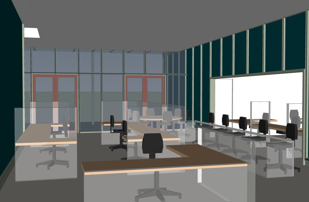
Space programming respected the historic floor plan and scale of the original structure and recreated Yeon’s original design intent of integrating indoor space with outdoor space. Extraneous equipment and unsympathetic additions were removed from both the interior and exterior. Interior design elements, furniture, and fixtures maintain the open gallery spacial quality while integrating new furniture and fixtures meeting the needs of the tenant. Major preservation focused on the exterior restoring original paint colors through serration studies, restoring building signage in original type style and design, preserving original wood windows, when present, and restoring the intimate courtyard with a restored operating water feature.

Case Study 2
120907 Lovejoy Pavillion 002
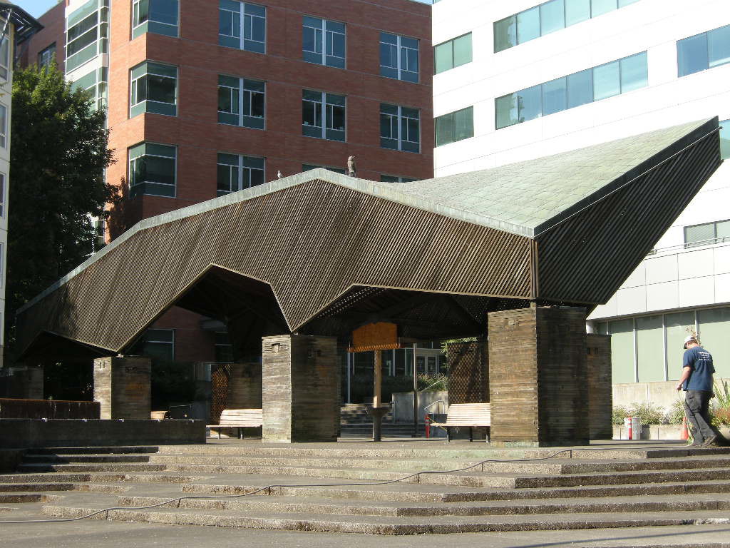
Moore, Lyndon, Turnbull & Whitaker’s 1965 Pavilion at Lawrence Halprin’s Lovejoy Fountain is a whimsical all wood structure with a copper shingle roof. Although a small structure, the pavilion represents a major mid-transitional work for Charles Moore as his design style moved from mid-century modern to Post-modern design. In keeping with the naturalistic design aesthetic established by Halprin, northwest wood species comprise the major structural system including the roof trusses, vertical post supports, and vertical cribs built from 2 x 4 members laid on their side and stacked.

Vertical loads are transferred from the trusses to the wood posts and spread to the wood cribs. Under the point loading, the cribs have compressed resulting in a sag or lean in the roof structure. Since the 2 x 4 wood members have crushed, they cannot be restored or salvaged as part of the restoration effort so new members were designed to replace the historic material.

120907 Lovejoy Pavillion 009
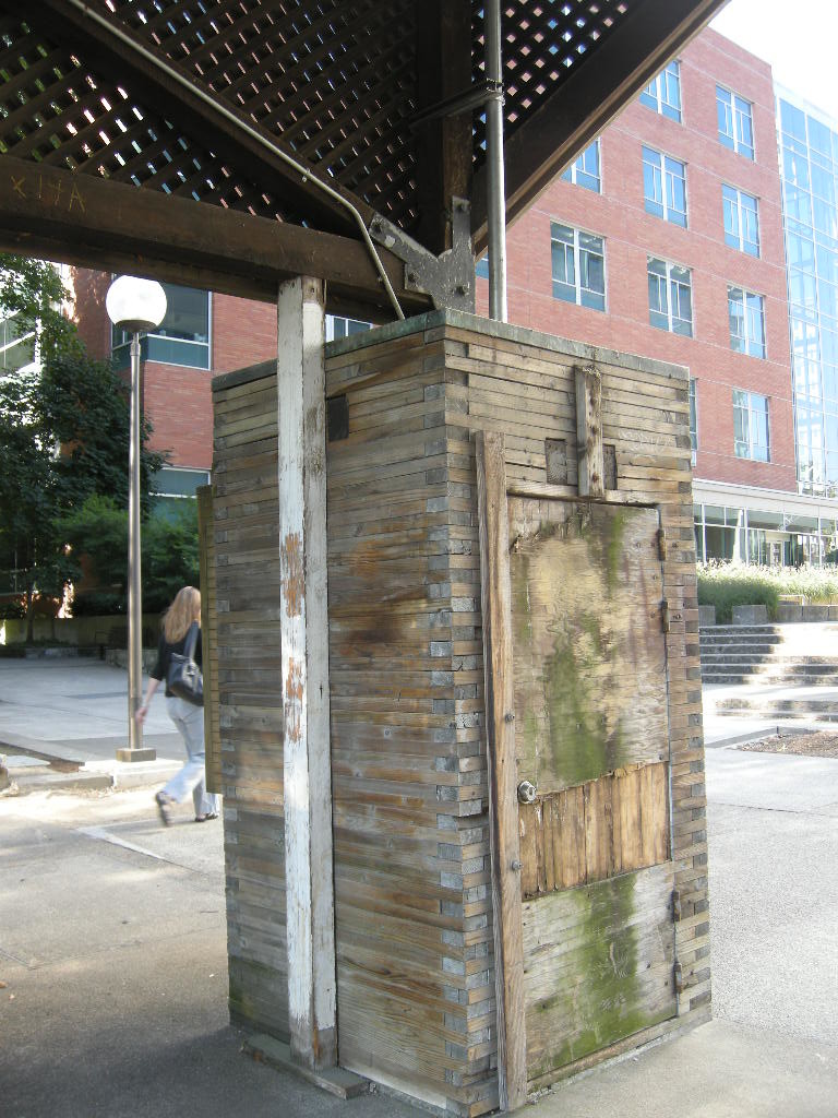
The restoration approach is intended to correct the structural deficiencies and replace the failed members with no changes to the historic appearance of the structure. The crib design allows for insertion of new steel elements, invisible from the exterior, capable of providing additional support for vertical loads. The difficulty arises because standard wood products available today have different visible and strength attributes from standard components available in 1965. Sourcing appropriate lumber is dependent upon clear and quantifiable specification, high quality inspection, and visual qualities. There are no structural standards for reclaimed or recycled lumber compounding the incorporation of “old growth” lumber as part of a new structural system. When original source material is no longer available, best practices for narrowing the selection of new materials will of necessity be combined with subjective visual qualities and a best-guess scenario as to how the new material will age in place similarly to the historic material. There are no single solutions so experience is key.

PMAPDX-survey-city-of-portlandCase Study 3
Whether or not Michael Graves’ Portland Building is considered a master work is greatly debated. Never the less, the building was nominated to the National Register of Historic Places after only 30 years and is recognizable around the world as THE building representing the start of Post Modernism. There is no debate to the fact that the building leaks. However, the method of building envelope repair could dramatically or minimally impact the exterior character defining features.

The façade of the Portland Building incorporates standardized aluminum single unit windows, aluminum windows ganged together to form a curtain wall, ceramic tile, and stucco veneer as the prominent construction materials. All of these systems or individual components are neither produced nor assembled currently in similar manners due to improvements in technology and building envelope science.

Proposals to improve envelop performance of both the individual window units and window systems are challenged in finding products that will both improve performance and retain the aesthetics of a Post Modern building. (i.e. retain the essence of criticism towards Post Modernism by preserving the appearance of insubstantial material installed as a thin veneer). Windows have always been a source of controversy in preservation and now the definition of windows has expanded to include curtain wall systems as the importance of preserving Recent Past and Modernism has entered into the mainstream.

When a structure, like the Portland Building, relies heavily on the expression of its skin as the character defining feature, off the shelf solutions for fixing envelop deficiencies must be expanded to include customization, façade impact studies, robust strategies for solving the issue, and out-of-the-box thinking by conservators, architects, historic consultants, and building envelope experts. A collaborative approach based on the original architect’s design intent must drive the decision making. It is an unusual approach, but original design intent will be a key factor when resolving façade problems on Modern and Post Modern structures.

Written by Peter Meijer AIA,NCARB, Principal
portlandbuilding-model