Tag Archives: pmapdx

The Historic Documentation of Umpqua Hall

Southwestern Oregon Community College hired Peter Meijer Architect in September 2017 to assist in the historic documentation of Umpqua Hall. This significant resource will be reconstructed as part of the college’s new Health and Science Technology Building, a project that will provide additional classroom space to support the college’s nursing and EMT programs. Umpqua Hall played a significant role as one of the first two buildings constructed on campus to serve as the primary location for the college’s vocational courses. Below is an excerpt from the documentation that PMA provided for the State Historic Preservation Office that assesses the historic significance of Umpqua Hall.

1972 ca._Umpqua Hall
HISTORY AND CONTEXT
Southwestern Oregon Community College was the first post-secondary education available to students on the Oregon Coast in the early 1960’s. It held its first classes in 1961 at the North Bend airport, and was relocated to its new home three years later. Prior to its establishment, students in this coastal area travelled long distances to be able to attend college, and many could not afford to go at all.

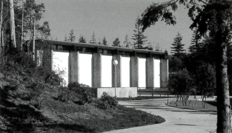
Southwestern Oregon Community College began as a vocational school with the mission of preparing the general population of Coos Bay to enter a workforce created mainly by the timber and fishing industries in the area. As the original “Shops Building”, Umpqua Hall was at the heart of this development. It was the primary building on campus to house many of the school’s vocational-technical programs. The automotive, welding, and carpentry shop classes that were a part of the Mechanics and Industrial program all took place in Umpqua Hall.

In the 1970’s, the college faced the dilemma of a changing market in Coos Bay. As housing development increased in the city and brought the opportunity for new businesses with it, minimum wage service-oriented jobs began to replace the higher paying manufacturing jobs that the college’s courses were tailored toward. Graduates of the programs offered at SWOCC were in less demand, and student enrollment began to decrease. As a result, SWOCC recognized a need to provide displaced workers—as well as veterans that were returning home from the Vietnam War and students seeking to later transfer to a university at an affordable cost—with the appropriate type of education required to compete in the changing economy.

The campus has since evolved to accommodate these economic changes. Umpqua Hall was retired from its academic function when the Automotive Technology program was eventually eliminated in 1994. The oldest buildings that still exist at SWOCC, namely Umpqua and Randolph Halls, represent a significant period of economic growth in the history of Coos Bay that played an indispensable role in the initial development of the city and in its educational options.

1964_Aerial view SWOCC with Randolph and Umpqua Halls only
UMPQUA HALL CONSTRUCTION TIMELINE
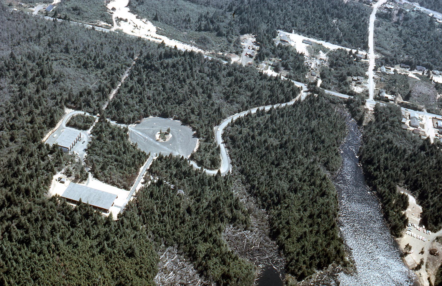
1963 to 1964—Umpqua and Randolph Halls, as well as parking lot #1 on the south side of campus, were constructed as part of Phase I of the 1963 six-phase Master Plan. Randolph Hall was known as the “Laboratory Building” that served as the main academic building. Umpqua Hall was known as the “Shops Building”, and originally functioned for vocational schooling that included automotive, carpentry, woodworking, and industrial technology classes.

1964 to Mid-1960’s—The campus underwent Phase II of the Master Plan that included Dellwood Hall (the administration building and temporary home of the library at the time), Coaledo Hall, Sitkum Hall, and parking lot #2.

1981—A storage outbuilding was built to the west of Umpqua Hall by this time, probably in the late 1970’s.

Circa 1985—The college planned to relocate the “Industrial Building” to a location northeast of Prosper Hall, but to keep the metal welding and auto diesel programs located in Umpqua Hall. The plan was to eventually phase out the use of Umpqua Hall.

1994—The Automotive Technology program in Umpqua Hall was eliminated, and the building was retired from academic purposes.

1994 to 1999—By this time, new buildings had been constructed northeast of Prosper Hall to accommodate for the retirement of Umpqua Hall. Fairview Hall held the new welding and manufacturing classrooms, and the new Lampa Hall housed what became known as the B-2 Technology Annex.

2005—Umpqua Hall had since been used for an assortment of different functions. At this point, the building served as the college’s computer networking and hardware instructional labs. As early as 2005, a Master Facility Plan mentioned that a design for a Health, Science, and Technology building was being considered, which would have resulted in the conversion of Umpqua Hall to additional campus storage and maintenance space for the Plant Operations department.

2008—As part of a potential $2,600,000 project to reintegrate Umpqua Hall, another Master Plan of the SWOCC campus proposed to rehabilitate the building to serve as the electronic lab and to hold AutoCAD and computer classes for students. This plan also proposed to add a Student Center Addition to the western side of Umpqua Hall. This proposal was not actualized.

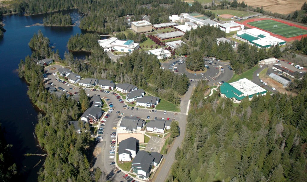
2017—Currently, Umpqua Hall is used for campus security operations and storage, and its western outbuilding serves as an auxiliary maintenance warehouse for Plant Operations. A new project to incorporate Umpqua Hall into the new Health, Science, and Technology building is underway.
southwestern-oregon-community-college-most-beautiful-campuses-1024x608
AT A GLANCE – PROPOSED PROJECT FOR UMPQUA HALL
The most substantial work proposed at the SWOCC campus is the reconstruction of and addition to Umpqua Hall, one of the college’s two oldest buildings, to develop the new Health & Science Technology Building (View 10). The outbuilding that sits west of Umpqua Hall will be demolished to make way for the construction of the new “west wing” addition. Both the interior and exterior of Umpqua Hall will be heavily altered to provide space for the program’s health and science classrooms and offices. A new “west wing” addition will also be built southwest of the Umpqua Building, and will more than quadruple the overall square footage of the new facility. The eastern end of the addition will intersect with the southern end of the existing building at a 90-degree angle. A large lecture hall will protrude from the northern façade of the addition.

Written by Kristen Minor / Associate, Preservation Planner with Marion Rosas / Designer

Long Term Impacts of Masonry Waterproofing Sealers

Product X works as a masonry sealer, but what are the long-term ramifications of using Product X on masonry buildings? Masonry sealers come in a wide variety of formulations, but how do the various chemical compositions react to environmental conditions and what affect does the formulation have on the masonry? Most masonry waterproofing sealers specified by architects and conservators, installed by contractors, and requested by property owners are based on Silicone (═Si═ ) chemistry. There are three popular groups of silicone based materials being used as waterproofing materials: 1) silicates, 2) the group of silane, siloxane, siliconate; and 3) silicones. Silicates, similar to Product X, provide waterproofing properties by filling the pore structure of building materials with silicon dioxide (SiO2) precipitation. Common silicates are sand, Portland cement, and other natural occurring minerals. Silanes, siloxanes and siliconates provide waterproofing properties by bonding with the substrate. They are often referred to as penetrating sealers. Silicones do not form chemical bonds with the substrate. Silicones provide waterproofing properties by forming a non-bonded film. Such products are labeled as thin-film sealers.
WSU-PMAPDX_masonry_sealers
SILICATES
Silicates are most commonly used in crystalline type water proofing agents for concrete. Their use is generally focused on concrete substrates. However, it is known that strongly alkaline, aqueous solutions of methyl silicates can be used to impregnate masonry. Such solutions often depend upon caustic soda for their alkalinity. Impregnation of masonry with such solutions is often disadvantageous, however, particularly due to the high alkalinity. For example, the high caustic soda content of the solution will cause a gradual removal of the organosilicon compounds from the interstices of the masonry by chemical combination with the surfaces of the masonry surrounding the interstitial voids. Moreover, the caustic soda solution reacts with carbon dioxide or other acidic components of the air which gives rise to salting out and the formation of efflorescence on the masonry. (1)

SILANE, SILOXANE, SILCONATES
Silane, siloxane, silconates are penetrating type of sealants. Their effectiveness is dependend on the porosity of the substrate and the dosage of repellant applied. Each manufacturer will have unique requirements for the application and dwell time of their sealer. Silanes and siloxanes form a chemical bond with siliceous containing materials. Silanes and siloxanes go through three reactions when applied to a masonry surface: hydroloysis, condensation, and bonding. During the condensation phase, the moisture vapor transmission rate is critical to preventing moisture accumulation behind the sealer layer.

With penetration type sealers, it is critical to the longevity of substrate (masonry) that the moisture vapor transmission of the sealer is actually known. There has been very little third party testing of vapor transmission and each product manufacturer provides varying ways of testing transmission. In addition, the active ingredient content of the sealer formulation and the coverage rate will greatly affect the moisture vapor transmission. In other words, performance in the field will vary greatly from highly controlled laboratory testing.

Siliconates are water soluble and they impart water repellency on porous surfaces. A drawback to using diluted siliconate solution for waterproofing applications is that siliconates react with carbon dioxide and carbonatious matters present in the substrate to form a water repellent, water-insoluble, white colored precipitate. This white layer may become quite visible and require aggressive removal procedures resulting in objectionable appearance or scarification of the surface during removal processes.

SILICONE
The effectiveness of silicone sealer depends on the alkyl group used (which directly influences its resistance to alkaline conditions), the amount of exposure to ultraviolet light and the level of moisture in the masonry when the silicone is applied. (2)

The proliferation of masonry coatings on the market, and the continued pervasive use of the coatings, requires the architect, engineer, contractor, and conservator become more knowledgeable on the wide variety of coating formulations, the continued evolution of those formulations, and understand both the right application of the product and potential detrimental effects of using the wrong product on historic substrates.

WSU-PMAPDX_masonry_sealers_002
CASE STUDY: WASHINGTON STATE UNIVERSITY, DUNCAN DUNN HALL
In preparation of a major renovation, Peter Meijer Architect, PC was retained in 2010 to conduct a general exterior condition assessment of Duncan Dunn Hall on the campus of Washington State University, Pullman, Washington.

Duncan Dunn was constructed in 1926 as a women’s dormitory for Washington State University, then named Washington State College. It is located in the heart of the WSU campus, facing north towards Linden Avenue. First known as the “New Dorm,” the building cost $150,000.00 to build at that time, and could house 140 students. The architect, Stanley Smith, was the head of the department of architectural engineering and was also the official University Architect.
WSU-PMAPDX_masonry_sealers-004
The predominant material present on Duncan Dunn is a solid brick unit, brownish red in color, and approximately 8” x 3 7/8” x 2 3/8” in size. At the time of assessment the brick had a very prominent unsightly, white coating over 60% of the masonry facades.

WSU-PMAPDX_masonry_sealers-003
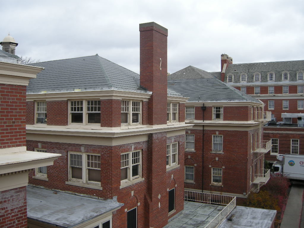
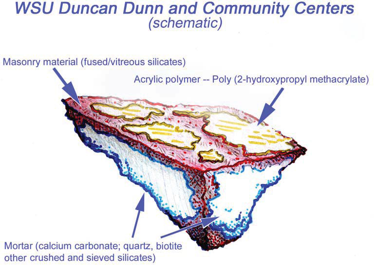
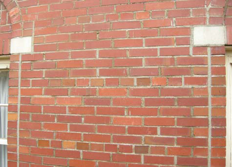
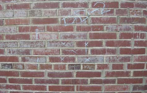
Believing the white haze was a result of UV degradation of a masonry sealer, PMA conducted Reunion Internationale des Laboratoires D’essais et de Recherches sur les Materiaux et les Constructions (RILEM) tube tests of water absorption on the exterior brick on Duncan Dunn Hall. The area of brick chosen for the test was out of direct sunlight to avoid affecting the results and was conducted during dry weather. No movement of the water over a 45 minute period was recorded during the test. Masonry units, even those constructed with high quality clays under controlled firing conditions will absorb some water. The results of the field test on Duncan Dunn, along with the white surface haze, reinforced the assumption of the presence of a masonry coating.

Communication with WSU personnel and their internal research surmised that “the building may have had a sealer put on after the original construction. [WSU cannot verify the application through original records] but do know [that a sealer] was not used on a regular basis after [construction completion.] Back in the 70’s some “miracle sealer” of some sort was introduced on Campus and used at a few locations. Duncan Dunn Hall was among the buildings [receiving masonry sealers.] Today you can see the remnants of this as a white powdery surface that almost looks like efflorescence. [WSU] does not know the name of [the sealer] product.”

To confirm the presence of the sealer, PMA conducted lab testing via polarized light microscopy (PLM) episcopic microscopy, capillary fusion and Fourier-transform infrared spectroscopy (FTIR) per ASTM D1245 and E1252, respectively. FTIR indicated the material to be Poly(2-hydroxypropyl methacrylate), an initially water-miscible acrylic polymer that in these samples is at present very brittle and sloughs rather easily.Testing confirmed the presence of a “water-miscible acrylic polymer”. Due to chemical breakdown under UV, the chalky coating remaining on Duncan Dunn is no longer soluble in water.Because of the insoluble nature of the white haze, low pressure hot-water cleaning methods would not be successful. PMA recommended the Rotec Vortex cleaning system using a mirco-abrasive mixture of dolomite, water, and air. Ultimately this removal processes was successful with no damage to the masonry surface.

(1) Patent application for new formulation of sealers. (2) Types of Masonry Water Repellents, GSA web site. Information derived from ProSoCo Inc. product literature.

Written by Peter Meijer AIA, NCARB / Principal

Analyzing Historic Masonry Wall Performance

Wilmer-Davis Hall is a residential complex on the Washington State University (WSU) Pullman campus. Built in 1937 by Architect Stanly Smith, with John Maloney, the six-story structure is composed of masonry and concrete with a masonry/brick veneer in the classical and Georgian Revival architectural styles. For a recent feasibility study of the complex, PMA provided an exterior assessment and a limited moisture study utilizing Wärme Und Feuchte Instationär (WUFI), an industry standard application in predicting wall performance to determine how additional insulation may impact the existing constructions and wall performance.

The primary concerns of this analysis included increased potential for freeze thaw action and increased mold growth as a result of added insulation. When historic buildings are insulated the insulation is typically added to the interior of the structure to prevent alterations to the exterior appearance. This often causes the outer layers of the wall to be both colder and wetter as the materials are no longer warmed and dried by the interior heating system. The additional water and more extreme temperatures can result in an increase in freeze thaw action, corrosion of metal reinforcement, and/or increased mold growth.

Additionally adding insulation to a wall changes the location of the dew point within that construction (the point at which vapor in the air condenses into water). A dew point within the middle of the wall can also result in increased moisture within the wall cavity. If a wall has difficulties drying due to any of the above causes it is possible that over the course of several years the quantity of water within the wall will consistently increase. Accumulation of water will exacerbate reinforcement corrosion and mold growth and can result in increased freeze thaw action. This study focused on the following metrics to analyze proposed wall performance: quantity of water in the assembly, quantity of water in each material layer, relative humidity in layers susceptible to mold growth, and isopleths.

MODEL SETUP
As in any simulation analysis a number of assumptions were made regarding the existing wall construction and the proposed design conditions. A variety of different conditions were analyzed in order to explore the range of conditions and variables. Below is a description of the inputs as well as an analysis of the results.

Four (4) proposed wall constructions were analyzed to determine how different types, quantities, and configurations of insulation would impact the existing constructions. The configurations were based on outlined solutions for meeting Washington State Energy Code (WSEC) or providing improved thermal comfort. Two of the proposed constructions meet WSEC (Option 1 and Option 2), while two of the solutions (Option A and Option B) fall short of fully meeting WSEC, but would provide improved insulation values. The options simulated included:

Base Case (Existing Conditions) (R-4.8)
3-1/2” Masonry
1” Air Gap
7-1/2” Hollow Clay Tile Back-Up Wall
1-1/2” Plaster

Option 1 (Meets WSEC) (R-15.4, continuous insulation)
3-1/2” Masonry
1” Air Gap
7-1/2” Hollow Clay Tile Back-Up Wall
1-1/2” Plaster
2” Expanded Polystyrene
Vapor Retarder (1perm)
0” Gypsum

Option 2 (Meets WSEC) (R-20.9, insulation is not continuous)
3-1/2” Masonry
1” Air Gap
7-1/2” Hollow Clay Tile Back-Up Wall
1-1/2” Plaster
3” Batt Insulation
0-1/2” Expanded Polystyrene
Vapor Retarder (1perm)
0-5/8” Gypsum

Option A (R 17.4, insulation is not continuous)
3-1/2” Masonry
1” Air Gap
7-1/2” Hollow Clay Tile Back-Up Wall
1-1/2 Plaster
2” Foamed-In-Place Polyurethane
Vapor Retarder (1perm)
0-5/8” Gypsum

Option B (R-18.4, insulation is not continuous)
3-1/2” Masonry
1” Air Gap
7-1/2” Hollow Clay Tile Back-Up Wall
1-1/2” Plaster
3-1/2” Batt Insulation
Vapor Retarder (1perm)
0-5/8” Gypsum

MATERIALSIt should be noted that no material testing was performed during this phase of the project – instead default material properties were chosen from the WUFI database. Materials used include:

  • Masonry: The material ‘Brick (Old)’ was used to simulate the existing masonry. The material is a generic historic brick material compiled from a variety of different bricks and included in the WUFI database.
  • Airspaces: All airspaces were modeled without additional moisture capacity which according to WUFI, models more realistic moisture storage in air cavities.
  • Hollow Clay Tile: The historic drawings indicate that behind the masonry is hollow clay tile. WUFI does not have a default material for hollow clay tile. Instead a masonry material ‘Red Matt Clay Brick’ was used to represent the solid portions of the clay tile. Air spaces were used to simulate the hollow portions of the tile.
  • Historic Plaster: The WUFI database does not have a default historic plaster material. The ‘Regular Lime Stucco’ material was used to simulate the existing plaster.
  • Batt Insulation: ‘Low Density Glass Fiber Batt Insulation’ was used in simulations.
  • Rigid Insulation/Expanded Polystrene: ‘Expanded Polystyrene’ was used in simulations.
  • Fomed-In-Place: ‘Sprayed Polyurethane Closed-Cell’ was used in simulations
  • Gypsum: ‘Interior Gypsum Board’ was used in simulations.


  • Weather/Interior Conditions In each simulation the model was set to mimic extreme situations to verify that the existing walls will perform in all conditions. The Spokane, Washington weather file indicates that the south elevation should have the most wind driven rain and moisture impacting the wall. Given this information the analysis used south exposure and the Spokane weather file to simulate exterior conditions. For the interior climate conditions the following profiles were used:

  • Interior temperatures ranging from 69 °F to 72 °F
  • Relative humidity ranging from 50% – 60%


  • The above values represent a relatively high moisture load which is consistent with the existing use as a residential facility.

    Water Intrusion Additionally as per ASHRAE 160 a small leak (1% of driving rain) was introduced into the exterior assembly to simulation a scenario where water was penetrating the exterior surface. This could occur at bondline failures in the mortar or penetrations through the wall assembly. The leak was placed past the masonry veneer on the face of the hollow clay tile backup wall.

    Initial Conditions Lastly the initial conditions of the materials were determined using ASHRAE 160. For existing wall materials EMC80 was used as the initial moisture content. (EMC80 is a value expressing an equilibrium of water and material masses at 80% humidity). For new components the expectation was that the materials would be installed from the interior and would remain dry during the construction process – thus EMC80 was used for new components as well.

    WUFI RESULTS
    Four metrics were used to interpret and analyze the following WUFI results: Total Water Content/Water Content in Material Layers, Temperature, Relative Humidity, and Isopleths.

    Total-Water-Contents-WSU-Wilmer-Davis-WUFI-Report-6
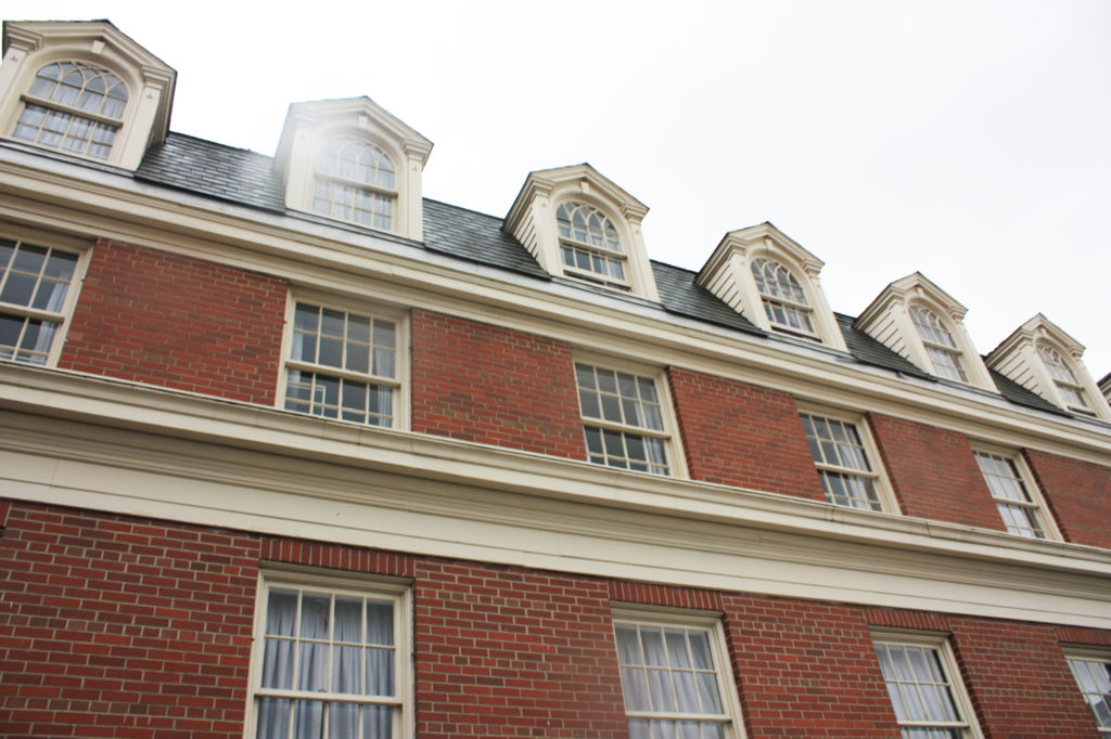
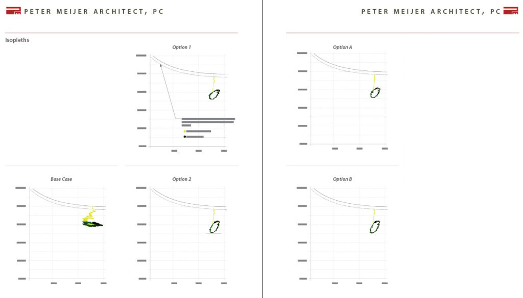
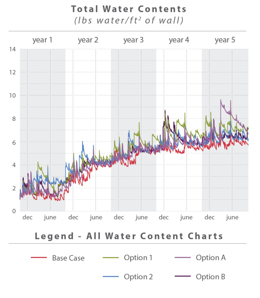
Total Water Content WUFI can predict the total accumulation of water over the time frame of the simulation, in this case five years. Over the course of each year a wall assembly will be wetted by the rain, and dry over the summer months. Differences in humidity and temperature between spaces may cause water condensation within the walls. If conditions do not allow condensation or other water to dry, materials may accumulate water over a period of time.

    The chart above shows how each of the different simulations performed. Note that total water content is measured per ft2 of wall. Walls that are thinner (existing construction) will inherently have less capacity to hold water. In general all of the walls performed in a similar manner – an indication that the retrofit strategies should perform in a comparable manner when compared to the existing walls. As can be seen in the chart, all of the simulations, including the base case showed some accumulation of water over the five year simulation. These results, however, do not conclusively show that the proposed walls will accumulate water. The results indicate that even the base case is accumulating water over time. During PMA’s site visit, however, the existing exterior walls appeared to be performing well – which would not be the case if they were consistently accumulating water. Additional analysis showed that the gradual accumulation of Total Water Content appears to be a result of initial instability within the wall construction that equalizes over time. A 20 year simulation showed accumulation over the first five years, after which the water content stabilizes.

    Water Content in Material Layers Each of the individual layers of material in a wall assembly have the capacity to hold and retain water. A high water content in any individual layer can indicate the potential for mold growth, the possibility for damage associated with freeze thaw, and a reduction in R-Value based on moisture content. Mold growth is possible when the moisture content is above 20% and if the material has the capacity to feed mold growth. The charts below show how each simulation performed for each layer within the wall.

    Water-Content-Materials-WSU-Wilmer-Davis-WUFI-ReportIn general most layers remained well below the 20% threshold for mold growth. The insulation layers, however, are an exception. Options 2 and B both had batt and/or foam insulation which yearly exceeded 20% water. This quantity of water is somewhat concerning for the batt insulation as it may reduce the material’s R-Value and/or contribute to mold growth depending on the composition of the material. Solutions that used foam insulation performed better than those with batt insulation.

    Temperature One common result of insulating a historic building from the interior is increased freeze thaw action. Insulation prevents the interior conditioned space from heating and drying the exterior masonry. As a result the masonry is typically saturated with more water and exposed to colder temperatures. The analysis looked at the temperature within the middle of the masonry to determine how added insulation would impact the material. A chart comparing the base case to the four options for insulation is located below. As can be seen the brick temperature remains consistent with the base case in all retrofit options. This is an indication that the masonry may not by exposed to additional weathering as a result of added interior insulation. It should be noted that not all masonry reacts to water saturation and freezing conditions in the same manner. To further analyze the masonry’s susceptibility to freeze-thaw action lab analysis is recommended to determine material performance. If results indicate that the masonry is susceptible to freeze-thaw it will be critical to ensure new constructions do not lead to a significantly colder/wetter exterior wall.

    Relative Humidity The relative humidity of the air within the wall construction also has an impact on material longevity and mold potential. A high relative humidity in plaster or batt insulation layers may indicate mold growth, while a high relative humidity in layers with reinforcement may indicate the potential for corrosion. A constant and high relative humidity (above 80%) indicates the potential for mold growth. The charts to the right focus on several susceptible layers, the existing plaster, batt insulation, and gypsum board. In general the majority of the layers susceptible to mold remained below 80% relative humidity, or consistently dropped below 80% relative humidity allowing the material to periodically dry. An exception was the existing plaster layer. The addition of interior insulation caused the relative humidity within the layer to increase approximately 15%, from 65% (base case) to just over 80% (all options for added insulation). This spike in relative humidity is concerning and could indicate the potential for mold growth within the layer.
    Materials-Temperature-Relative-Humidity-WSU-Wilmer-Davis-WUFI-Report
    Isopleths WUFI can also predict mold growth by plotting isopleths on the interior surface. The isopleths are plots of the temperature and the relative humidity for every time period calculation. When the temperature and relative humidity both exceed the limiting lines calculated by WUFI there is the potential for mold growth. The simulations indicate that there is very little potential for mold growth. All of the simulations begin above the limiting lines, but over time equalize and remain well below the threshold calculated by WUFI.
    wufi-isopleths-results-wsu
    CONCLUSIONS
    The results described above indicate that there could be some challenges to designing an appropriate insulation system for Wilmer Davis Hall. Three of the primary concerns noted in the above analysis are: increasing total water content quantities; high quantities of water in the batt insulation layers; and consistently high relative humidity’s in the existing plaster layer.

    In general Option 1 and Option A performed better than Option 2 and Option B – primarily because they relied on only foam/rigid insulation. This resulted in no risk of mold growth within the insulation layers and no reduction of the R-Value. Concerns were still identified with both Options in terms of total water content and relative humidity in the plaster layer.

    Prior to detailing a new wall for construction additional analysis is recommended. Minor changes in material properties can have significant impacts on wall performance. The above analysis has indicated that there is a potential for mold growth, but has not confirmed its likelihood. Most of the metrics indicated no risk of mold growth – however because some of the metrics showed a potential for mold, additional analysis is recommended. Testing of the existing materials and specific data on proposed products should be used to refine this analysis and determine extent of mold growth risk.


    Written by Halla Hoffer,AIA, Assoc. DBIA / Associate, Architect

    2016 Year in Review

    As we look back over the past year and reflect on our completed, on-going, and upcoming projects, we’d like to take the opportunity to say we have truly enjoyed collaborating and communicating with you!!
    pmapdx-2016-holiday

    2016 PROJECT HIGHLIGHTS
    PMA-2016-year-in-review
    From top, left to right: Studio Building Exterior + Window Assessment (Portland, OR); Joseph Vance Building Exterior Envelope Repair (Seattle, WA); PPS Grant High School Modernization (Portland, OR); SPS Magnolia School Renovation (Seattle, WA)

    PMA HAPPENINGS
    2015-2016-Halla-HWe are excited to announce: Halla Hoffer, Associate, successfully passed her ARE and is a licensed Architect in the state of Oregon.

    Halla is passionate about rehabilitating historic and existing architecture – integrating the latest energy technologies to maintain the structures inherent sustainability.

    PMAPDX-silver-to-goldWe are committed to the reuse and adaptability of existing resources, and in 2016 moved from Silver to Gold certification!

    Post Modern Building Materials Part Two

    Post Modern Architecture: Documentation and Conservation
    At the DoCoMoMo US, Modern Matters, conference April 2013 in Sarasota, Florida, DoCoMoMo Oregon presented a debate on the merits of Michael Graves Portland Building and on the larger context of Post Modernism in general. A lively debate at the end of the presentation centered on the merits of DoCoMoMo incorporating Post Modern under the mission of the organization. In general, the support, or lack of support, for an expanded interpretation separated into two distinct viewpoints. The division represented the difference between individuals that look at Post Modernism as a historic event and individuals that still perceive Post Modernism as bad design even if executed within their own practice.
    pomo-part-two-document
    In a seemingly short period of time, a lot has transpired since 2013 regarding the conservation of Post Modernism. After a presentation on Post Modernism: Are You Prepared to Protect It during the Modern Heritage track at the October 2014 Association for Preservation Technology (APT) Conference in Quebec City, the APT Board unanimously supported the need to get ahead of the technical issues associated with preserving Post Modern architecture.

    And in December 2015, the Princeton School of Architecture, educational forum for Michael Graves, hosted the Postmodern Procedures Conference. Described in the conference outline, there was a “particular emphasis on methods of documentation and analysis, technical and narrative drawing” related to Postmodern. Post Modern works, buildings, sites, and neighborhoods, as well as art works, are recognized as important design styles deserving conservation and further understanding of construction techniques. And many iconic structures are being negatively modified (Richard Meier, Bronx Development Center, 1977) or lost entirely (James Wines, Sculpture in the Environment (SITE), Best Product Stores, circa 1976). <1>

    Post Modern design was broadly practiced in both the United States and internationally. Large and small firms were attracted to the stylistic incorporation of classical western design vocabulary in stark juxtaposition against the plain, unadorned, square box that many argued architecture had become. Post Modern architects, engineers, and material suppliers were pushing new materials and innovative construction technologies as a way to create Post Modern design elements. Continuous innovation in building skins reintroduced porcelain enamel panels, a product brought by Lustron to the building industry during the housing boom following World War II. New skins made from Glass Fibre Resin (GFR) capable of being molded in classical curves and ornamental shapes favored by Post Modern design were created. Innovations in brick technology including large scale brick panels made from a single wythe of masonry to panels whose outer face was only one half inch of masonry, or thin bricks. Improvements in resins created new wood or simulated wood products and adhesives for mounting faux finishes to structural systems. Perhaps one of the more ubiquitous new materials used in the creation of Post Modern architecture was the faux stucco product Dryvit, an Exterior Finish Insulation System (EIFS). Like porcelain enamel panels, EIFS was introduced as insulated wall assemblies as a means to improve energy performance during the world’s energy crisis of the 1970s.

    Outside of dramatic assembly failures, particularly within the EIFS industry, that provide insight into Post Modern material and assemblies, much technological information has been relegated to the historical archives. Many Post Modern buildings incorporate systems or components that are neither produced nor currently assembled in similar manners due to improvements in technology and building envelope science. Therefore, the process and method of building restoration, rehabilitation, and/or focused envelope repair could dramatically impact the exterior character of Post Modern structures.

    Focusing on one popular building skin material, Alucobond, much in use during the 1980s provides insight into the need for more research and deeper understanding of Post Modern assemblies and how to conserve and protect these systems.
    portland-building-materials-detail
    Origins & Development
    Alucobond falls into the category of aluminum composite panels (ACP) or sandwich panels. Alcan Composites & Alusuisse invented aluminum composites in 1964 and commercial production of Alucobond commenced in 1969, followed by Dibond in 1989.<2> ACPs are used in a variety of industries ranging from aerospace to construction. Perhaps the most well recognized structure using ACP is the Epcot Center’s Space Ship Earth built in 1982. However, it is the work of Richard Meier and I.M. Pei during the 1980s that brought Alucobond into the forefront as an architectural cladding material. Several different skin materials are available including aluminum, zinc, copper, titanium and stainless steel.

    Manufacturing
    The major aluminum raw ingredient, bauxite, is mined throughout the world with US sources coming from Georgia, Jamaica, and Haiti. Processing of the bauxite predominantly occurs near the ocean ports, like Corpus Christi, where the raw material is off loaded. Manufacturing starts from either solid blocks of aluminum made into coil sheets or directly from pre-manufactured coil sheets. Assembly occurs along a continuous operating line that bonds the weather (exterior) and interior faces to the core, cuts the panel to length, and produces special shapes as needed.

    Aluminum Composite Panels (ACP) are high-performance wall cladding products typically consisting of two sheets of nominal 0.020″ (0.50 mm) aluminum permanently bonded to an extruded thermoplastic core (polyethylene). Assemblies in the mid-1980s would often consist of curtain wall sub-components with sheets of aluminum on the exterior and insulation placed behind the aluminum sheets. (See fig)

    ACP can be roll formed to curve configurations for column covers, architectural bullnoses, radius-building corners and other applications requiring radius forming. This process can be accomplished with a “pyramid” roll forming machine, which consists of three motor-driven adjustable rollers. You can successfully roll form ACP using machines with minimum 2 1/2″ (64 mm) diameter rolls. The operator normally makes multiple passes of the panel through the rollers to gradually obtain the desired radius. <3>
    pomo-part-two-methods-install
    Use & Methods of Installation
    Post Modern assemblies generally assumed water would get behind the face aluminum panel and need a weep path to exit the system. Air gaps were incorporated to induce drying and allow for weeping via gravity. Wind loads were accommodated through additional brackets, or stiffeners, set behind the face panel and connected to sub-framing. Much of the technology was based on curtain wall knowledge.

    The panel systems could often be complex in the attachment to the structure, but the face panels were very similar to panels of today.

    Conservation
    Deterioration mechanism are generally associated with the system assembly and rarely are there failures in individual panels beyond cosmetic damages to the face aluminum including fading colors, scratches, and impact damages. More often incorrect fasteners were used that create galvanic reaction between the fastener and aluminum panel or inadequate fasteners were used to accommodate structural loads. The lack of design for thermal movement between panels, over the height and length of the panel façade, or along edge interfaces with sealants are also key areas of assembly failures.

    Fortunately manufactures of Alucobond, or other aluminum composite panels, are still manufacturing the panel and components making in-kind replacement a viable conservation option. Inadequate structural systems can be reinforced through disassembly of the ACP for access to the structural support. Laser scanning technology has greatly enhanced the accuracy of recording existing conditions and is critical in reproducing replacement panels. Although labor intensive, most of the systems were attached using stainless steel fasteners. Like modern curtain walls, sealant and gaskets will be removed during disassembly and require reinstallation.

    Repainting or repairing surface defects is feasible but the results generally do not achieve the same quality of finish as the factory applied coating process. And as with all repainting projects, surface preparation is critical to the long-term success of the project.

    Loss of original Post Modern aluminum composite panel systems can be reduced through an increasing interest and research into the original design intent and assembly techniques. ACP were incorporated into Post modern structures because of the simplicity to create the curved forms and for rapid pace of construction. The systems are an important part of understanding Post Modernism and worthy of Conservation.

    Marquette Plaza (historic photograph)

    Marquette Plaza (historic photograph)

    Written by Peter Meijer, AIA, NCARB, Principal

    Preservation and Ballparks: A Survival Guide for the
    American Ballpark

    Since the creation of the ballpark in 1862 and the much later inception of the National Preservation Act of 1966, preservation and ballparks have not necessarily been synonymous with each other, especially when referring to those used for Major League Baseball. To further the point, of the 109 stadiums, ballparks, or fields used by Major League Baseball since 1876, only 43 exist today, and of those 43, only 9 are 50 years of age or older. This does not mean, however, that only 9 Major League Baseball stadiums have ever reached or even surpassed 50 years of age; it just means that meeting one of the most fundamental benchmarks in preservation does not guarantee survival. For that matter, neither does being listed on the National Register of Historic Places. Although preservation is practiced and taught through the lens of the National Park Service’s preservation standards, there are multiple factors that contribute to the preservation of a historic resource. Like anything, there is rarely, if ever, a single answer to solving a complex issue. This leaves the question, if not the existing preservation framework, what factors do contribute to the preservation of historic resources, specifically historic major league ballparks?
    baseball-historic-stadiums-pmapdx
    Though an intriguing question, it will not be completely answered in this observational study, given the number of variables for each resource. However, by analyzing the 9 existing Major League Baseball stadiums that have survived to reach the age of 50, Fenway Park (1912), Wrigley Field (1914), Los Angeles Memorial Coliseum (1923), RFK Stadium (1961), Hiram Bithorn Stadium (1962), Dodgers Stadium (1964), The Astrodome (1944), Angel Stadium (1966), and the Oakland Coliseum (1966), this study begins to quantify what factors have contributed to their prolonged survival and identifies two common elements: function and adaptability. This study also provides information that can be useful in steering and focusing preservation efforts toward the successful preservation of baseball stadiums, ballparks, and fields. Nevertheless, it should also be understood that, though the findings of this study identify patters of preservation, these patterns should not be used to determine historic significance or integrity.

    Elements of Survival
    The first and most obvious element of survival for the 9 historic Major League Baseball stadiums is their function. No function, no purpose. Easily said and just as easily true. Of the 9 existing historic ballparks, 8 are currently being use by a Major League Baseball franchise or other sports program, as they were originally intended. The Astrodome is the only ballpark of the 9 that is currently vacant. With the exception of the Astrodome, which is pending rehabilitation, 8 out of 9 (88.9%) of all historic ballparks are functional. Whether through baseball, football, or soccer, keeping ballparks functional will not only contribute to their purpose for existence, but can keep them extant. In cases where Major League Baseball franchises or other sports programs build new stadiums, relocate, or disband, it is critical that the existing or remaining ballpark, stadium, or field finds a function, preferably one that utilizes its original design intent. Without it, its odds of demolition are significantly increased, regardless of its age, history, or cultural importance.

    Ballpark Styles
    Another common element of survival that these historic ballparks share is their ability to adapt to an evolving sport and culture through alterations. Though this use of alteration, in terms of renovation or rehabilitation, is a common standard within the National Park Service’s preservation rubric, ballparks are unlike other architectural forms because they are in a constant discourse with the sport of baseball, which has historically contributed to their continued evolution. Out of this relationship, four primary ballpark styles were created: The Pre-Classic (1871-1909), Classic (1909-1953), Modern (1953-1992), and Retro (1992–present). These styles, from the modest, wooden, Pre-Classic ballpark to the predominant, contemporary, Retro style ballpark, are equally representative of the sport and our society during their time of construction, thus contributing to their demolition when both evolved. Given this inherent fate, ballpark demolition is as common to the sport as superstition. So common, that an average of 16 ballparks have been demolished during each stylistic trend. However, those that have defied this characteristic have done so through their ability to mend both sport and cultural trend by adaptation.

    Ballpark Alterations
    After analyzing the histories of each of the 9 historic ballparks, 100% have undergone some form of alteration in pursuit of modernity. The most common alteration made was the addition or renovation of seating. The least common alterations made were the addition of kids’ play areas and the addition or renovation of dugouts. These statistics are expanded in the Historic Ballpark Alteration Chart. This chart shows past, undergoing, and projected alterations to each of the 9 historic ballparks observed in this study. Depending on age, these alterations, which include renovations and additions, may have been made to the same ballpark more than once.
    Historic-Ballpark-Alteration-Chart_PMAPDX
    Overall, these alterations have unquestionably contributed to the extended lifespan of each of these ballparks. This has allowed 5 of them to obtain historic status, either nationally or locally, one of which used Federal Historic Preservation Tax Credits. More importantly, they all have retained their function and purpose, while not all alterations made to these ballparks align with the National Park Service’s preservation standards.

    Titled “Preservation and Ballparks: A Survival Guide for the American Ballpark,” this study is meant to propel the discussion of the question: what factors contribute to the preservation of major league ballparks? Other factors that need further examination to truly understand the holistic approach to preserving ballparks are: 1) the financial impacts of preserving, redeveloping, or repurposing a ballpark; 2) the impact that a ballpark has on team success, franchise revenue, location and fan base; 3) and local preservation laws and ordinances for historic resources. Additionally, for further statistical analysis, this study would need a larger sample size, which includes historic minor league ballparks.

    Overall, this study reinforces some of the most important and fundamentally crucial elements in preservation: function and adaptability. Though the findings made in this study are not new to the preservation field, the perspective of what elements contribute to preservation of a single utilitarian form, such as the ballpark, is. More importantly, this study also reinforces the necessity for change and growth for all structures, even if falling outside of national preservation standards. This does not mean that with change comes demolition, but that change should be embraced, as it has been for these 9 major league ballparks.

    Written by Brandon J. Grilc, Preservation Specialist

    Bibliography
    Ballparks of Baseball. Dodgers Stadium. http://www.ballparksofbaseball.com/nl/DodgerStadium.htm.

    Ballparks of Baseball. RFK Stadium. http://www.ballparksofbaseball.com/past/RFKStadium.htm.

    Charleton, James H. Los Angeles Memorial Coliseum National Register of Historic Places Nomination Form. Washington D.C.: National Park Service, 1984.

    Chicago Cubs. History. http://chicago.cubs.mlb.com/chc/ballpark/information/index.jsp?content=history.

    Chicago Cubs. Construction Timeline. http://cubs.mlb.com/chc/restore-wrigley/updates/timeline/.

    Cook, Murray. “Murray Cook’s Field & Ballpark Blog,” Hiram Bithorn Stadium Upgrades for 2010 (blog), May 26, 2010. http://groundskeeper.mlblogs.com/?s=hiram+bithorn+stadium.

    Donovan, Leslie, Rachel Consolloy Nugent, Erika Tarlin, and Betsy Friedberg. Fenway Park National Register of Historic Places Nomination Form. Washington D.C.: National Park Service, 2012.

    Georgatos Dennis. “Renovations Reshaping Oakland Coliseum.” http://www.apnewsarchive.com/1996/Renovations-Reshaping-Oakland-Coliseum/id-d9a080536647dd0a356dcbd51efd4095.

    Grilc, Brandon J. “Stealing Home: How American Society Preserves Major League Baseball Stadiums, Ballparks, & Fields.” Thesis., University of Oregon, 2014.

    Los Angeles Angels of Anaheim. Angel Stadium History. http://losangeles.angels.mlb.com/ana/ballpark/information/index.jsp?content=history.

    Los Angeles Dodgers. Dodger Stadium History. http://losangeles.dodgers.mlb.com/la/ballpark/information/index.jsp?content=history.

    Los Angeles Dodgers. Dodger Stadium Upgrades. http://losangeles.dodgers.mlb.com/la/ballpark/stadium_upgrades/.

    Melendez, Sara T. Aponte. Hiram Bithorn Municipal Stadium National Register of Historic Places Nomination Form. Washington D.C.: National Park Service, 2013.

    Powell, Ted. The Astrodome National Register of Historic Places Nomination Form. Washington D.C.: National Park Service, 2013.

    Sillcox, Scott. Heritage Uniforms and Jerseys: A celebration of historic NFL, MLB, NHL, NCAA football and CFL uniforms and stadiums/ballparks/arenas. http://blog.heritagesportsart.com/

    University of Southern California. The Coliseum Renovation. http://coliseumrenovation.com/overview.

    PMAPDX 2015 Year in Review

    HAPPY HOLIDAYS!!

    PMAPDX-Holiday-2015

    Wishing you a holiday season filled with cheer and delight from Peter Meijer Architect.

    As we look back over the past year and reflect on our completed, on-going, and upcoming projects, we’d like to take the opportunity to say we have truly enjoyed collaborating and communicating with you.

    2015 PROJECT HIGHLIGHTS
    OHSU-2015-PMAPDX


    Pacific-Tower-Rehabilitation-PMAPDX


    City-of-LO-CRU-ILS-PMAPDX

    PMA HAPPENINGS
    Peter Meijer AIA, NCARB, was a Presenter at the RCI, Inc. 2015 Symposium on Building Envelope Technology. He presented on, When Field Performance of Masonry Does Not Correlate with Lab Test Results. PPS Grant High School was the case study presented.

    Kristen Minor, Preservation Planner, is the newest member of the City of Portland Historic Landmarks Commission.

    Navigating the Historic Tax Credit Application

    Historic Tax Credits were founded in partnership with the National Park Service (NPS) and the Internal Revenue Service (IRS) in 1986. As one of a number of incentives to help owners preserve historic properties, Historic Tax Credits have since become the premier financial incentive towards the rehabilitation of income-producing historic properties. Historic Tax Credits can be used for older, non-historic properties as well, so long as they are income-producing, at a lower credit amount. An owner can receive a 20% rehabilitation tax credit for the amount spent on the qualifying rehabilitation of a National Register-listed property, or 10% tax credit for the amount spent on the qualifying rehabilitation of an older property with no historic status.

    There is a minimum threshold of rehabilitation investment that must be met in order to qualify. Rehabilitation project costs must be equal to the Real Market Value (as assessed by the local tax authority) minus the value of the land or $5000, whichever is greater. Rehabilitation Tax Credits for tax-exempt historic properties are possible provided that the investment partner using the tax credits is a for profit, tax paying entity. Typically, separate Limited Liability Corporations are established through which rehabilitation funding flows to the project.
    Pacific-Tower-Tax-Credits20% Rehabilitation Tax Credit
    The most common use of historic tax credits is the 20% Rehabilitation Tax Credit. To qualify for the 20% historic tax credit a property must be listed on the National Register of Historic Places either individually or as a contributing resource within a historic district. Properties must be a building as defined by Treasury Regulation 1.48-1(e), income producing, and undergo a certified rehabilitation process, which is evaluated by the NPS and the State Historic Preservation Office (SHPO). This process includes the completion of a three part application: Part 1-Evauation of Significance (not typically necessary if the building is already on the National Register); Part 2-Description of Rehabilitation; and Part 3-Request for Certification of Completed Work. Once completed and approved by the NPS the 20% tax credit can be claimed for the tax year in which the property was certified by the NPS. Tax credits can be taken in phases as well, as long as each phase meets certain conditions.

    10% Rehabilitation Tax Credit
    To qualify for the 10% rehabilitation tax credit a property must have been built before 1936. Properties eligible for the 10% tax credit must be buildings, income producing, non-residential, and remain on the original site. Historic properties that have been relocated do not qualify. Other conditions include the retention of at least 50% of the external walls, at least 75% of internal and external walls, and at least 75% of the internal framework. Unlike the application process for the 20% Historic Tax Credit, there is no formal review process or certification. However, the tax credits are redeemed the same way. Buildings listed individually or contributing resources within a Historic District on the National Register of Historic Places are not eligible for the 10% tax credit.

    Current Trends
    The staff at PMA have years of experience navigating the Historic Tax Credit application, placing properties on the National Register of Historic Places, and working with the State Historic Preservation Office and the National Park Service to assure the rehabilitation project qualifies and receives historic tax credits.
    US-Custom-House-Tax-Credit
    From initial application of Part I through final certification of Part III, 180 days or more can elapse. Current development practices and financial investment processes place pressure on the development schedule to initiate rehabilitation prior to final approval by the National Park Service. Early construction places the tax credit under risk and final approval can be withheld pending review of all rehabilitation impacts. Market demand for open space with exposed mechanical, electrical, and plumbing systems is creating a trend in rehabilitation of historic properties to expose these functional systems.

    PMA’s experience in working with the market demand and reaction to the trend by SHPO and NPS, can provide owners with advice on where reviewers will be more stringent. PMA has worked with NPS when a Condition of Approval was placed on the submitted Part 2 Description of Rehabilitation requesting alteration of completed ceiling conditions throughout the building in occupied space. Although the owner did know that construction prior to approval was a risk, they also needed to have some spaces complete in order to retain certain tenants and meet the financial loan terms. PMA sought a compromise with NPS retaining completed ceilings, but altering the design intent and finish in those spaces not yet complete in order to meet the new Condition of Approval.
    usch_Ground Floor_Northeast Room (Viewing Northwest)
    Similarly, PMA has noted in the Part II application process an acceptance of exposed fire sprinkler lines and exposed conduits but resistance to exposed ductwork and exposed cable trays. Whereas it could be argued that exposed mechanical and wiring systems are akin to exposed electrical systems in that the exposed work does not have a long-term impact on the historic walls, floors, and ceilings, the combined affect changes the subjective visual impact from NPS perspective.

    Each of the above trends requires diligent documentation and on-going discussion during the construction process, which, in itself, can be very fluid and entail rapid changes. The tax credit consultant must be skilled in communication and work with both the development team and tax credit reviewers.

    PMA Technical Assistance
    PMA is proud to undertake historic tax credit commissions as these projects have been a great way for our office to combine our specializations in architecture and preservation. Over the last five years, PMA has completed numerous Historic Tax Credit applications throughout Oregon and Washington. Overall, Historic Tax Credits have proven to be vital to the financial proforma and successful investment strategy to preserve and rehabilitate historic properties.
    Pac-Tower-Tax-Credit

    Written by Peter Meijer AIA, NCARB, Principal / Kristen Minor, Preservation Planner / Brandon Grilc, Preservation Specialist

    Modern Residential Building Styles

    city-of-olympia-survey-pmapdxBuildings constructed before 1965 have reached the age of eligibility for being considered historic by the standards of the National Register. That means that much of Modern Architecture, the general period ranging from 1950 through 1970, is historic, or soon will be considered historic as the 50-year mark is crossed. As historians assess and study Modern Architecture, we provide ever more precise descriptions and terms to describe the sub-styles and variations within the large umbrella term, “Modern.” As in taxonomy, which classifies and categorizes living organisms, we can recognize and assign groups of similar resources together for study.

    Modern architecture had its roots after World War I as part of an egalitarian movement. The new architecture looked to industrial materials and processes to replace painstaking handwork; a horizontal proportion and deliberate embrace of the ground plane as opposed to a formal, vertical building proportion; and the rejection of ornamentation.

    A Mid-Century Residential Survey in the City of Olympia

    PMA has been working on a Mid-Century Residential survey in the City of Olympia. The date of construction for resources surveyed is limited to a two-decade span from 1945 to 1965, and the building type is limited to single-family residential. Surprisingly, there are more individual sub-styles found in this survey than were identified in a more broadly focused survey, our 2013 Mid-Century non-residential survey in St Louis, MO. The reason for this is that the tight focus of study allows for classification based on more specific characteristics.
    WWII cottage-city-of-olympia-survey-pmapdx
    The St. Louis survey identified resources constructed from 1945 to 1975 as being either Moderne, Brutalist, International Style, New Formalist, Neo-Expressionist, or simply “Modern Movement” if the style could not be placed in any sub-style. A few had mixed characteristics. The wide variety of building types in the survey, including churches, high-rise towers, and industrial buildings, kept style classifications necessarily broad. Local variations of styles were observed and identified, but were not given their own identifying style name. A future regional survey of the same time period could invite more stylistic classification, if there were enough similar resources to compare.

    The Olympia Mid-Century Residential survey covers approximately 400 single-family homes. The variations in style identified might be described in an overview as belonging to one of three “families.” Transitional Modern includes Stripped Classical, Minimal Traditional, and World War II-Era Cottage styles. The second group is Ranch style, which covers a broad range of sub-styles and forms, including Split-Level or Split-Entry Ranch; Contemporary Ranch; Storybook Ranch; and Colonial or Early American Ranch. The last group is a Neo-Expressionist collection of styles that were primarily constructed starting about 1965. These styles include A-Frame, Shed, Geodesic Dome, neo-Futurist, Pavilion, and other eclectic explorations and celebrations of building technology and structure. While none of these Neo-Expressionist styles were identified in the Olympia Mid-Century Residential survey, PMA expects at least one of these (Shed style) to be identified in urban Olympia if the time period studied is extended beyond 1965. Also, many of these styles were constructed in more rural areas than the concentrated Mid-Century neighborhoods examined in the survey. It is possible that Neo-Expressionist residences will come to light with further survey and exploration.

    Min-Traditional-city-of-olympia-survey-pmapdx
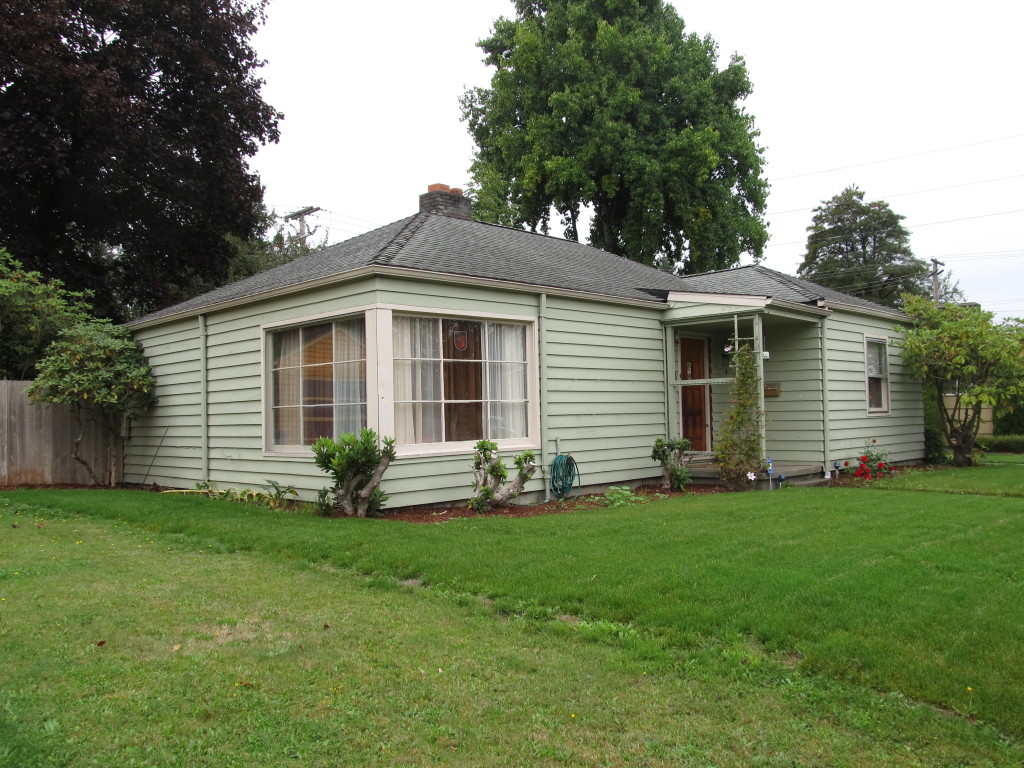
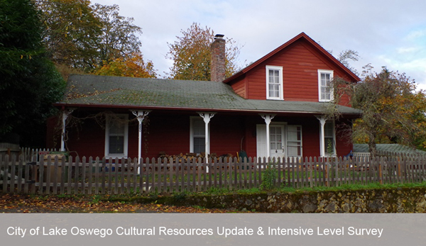
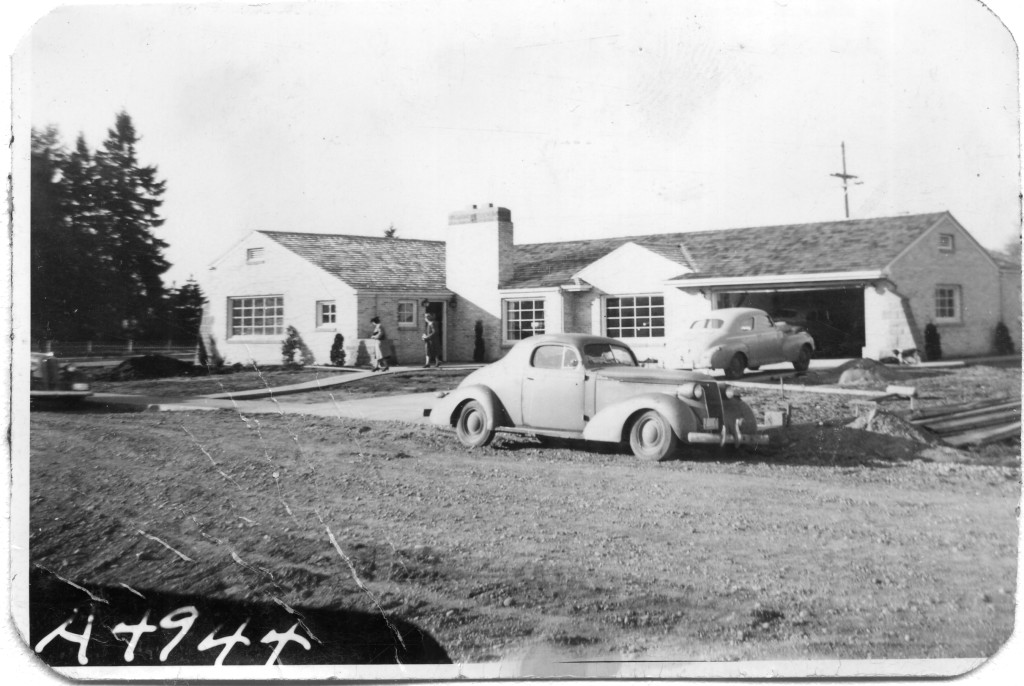
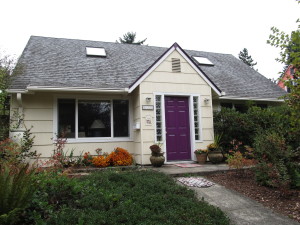
The Olympia survey classified the first grouping of styles as those that are transitional. Transitional Modern styles have some elements of Modern and some elements of more traditional architecture. Windows might be vertically-oriented, double-hung wood windows (traditional) rather than having horizontal proportions (Modern). A roof might be a moderate pitch, with minimal overhangs (traditional), rather than a shallow pitch with outwardly-extending gables (Modern). In Olympia, 37% of the houses surveyed were Modern Minimal Traditional, by far the most prevalent Transitional Modern style.

    Ranch-city-of-olympia-survey-pmapdx
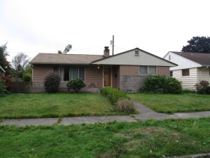
Ranch style architecture is the style that architecture critics have generally spurned, since houses were often constructed by contractors without architect’s involvement. Ranch buildings are broad, one-story, and horizontal in overall proportion. They have an attached garage which faces the street and is part of the overall form of the house, and almost always a large picture window facing the street as well. Cladding is used to accentuate the horizontal lines of the house, so there is often a change in material at the lower part of the front façade- brick veneer was a popular choice. Many of the sub-styles of Ranch architecture are “styled” Ranch houses, meaning that elements from another style of architecture were placed on a Ranch form building. One example is Storybook Ranch, which uses “gingerbread” trim, dormers or a cross-gable, and sometimes diamond-pane windows. Are these decorated sub-styles still part of the canon of Modern Architecture? In many ways, they are more Post-Modern than Modern, but that distinction is worthy of an involved discussion of its own.

    Split-level-city-of-olympia-survey-pmapdx
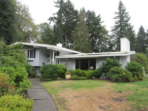
The Olympia Mid-Century Residential survey found over half the resources surveyed to be Ranch or variants of Ranch style. 31% of the surveyed homes were identified as simply Ranch, with another 11% Early Ranch, 9% Contemporary Ranch, 4% Split-Level or Split-Entry, and 4% one of the “Styled” Ranch variations. Sheer numbers alone remind us that the Ranch is deserving of study and shows us how the majority of middle-class Americans lived. As Alan Hess writes in his book Ranch House,

    “Most critics overlooked or ignored the prototypical Ranch house architecture, the variety of its manifestations, the social complexity of its neighborhoods, and the tract Ranch’s often innovative mass-construction methods. To most critics living in traditional cities with little contact with the conditions, desires, and apparent satisfactions of middle-class suburban life, the suburbs were a foreign land.”

    The more we study these styles of Modern residential architecture, the more they may be appreciated, celebrated, and well-maintained. And if you live in or grew up in a Ranch style house, it is now potentially historic.
    cropped_orig elev-city-of-olympia-survey-pmapdx

    Written by Kristen Minor, Preservation Planner. For additional MCM survey projects, please visit our STL Modern Non-Residential Survey project.

    Sustainable Housing: High Desert Design

    Eco-Huts for Warm Springs Tribes

    Warm-Springs-ProForma-pmapdx-design
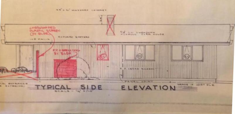
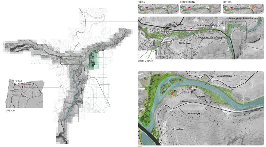
Projects that integrate building science, stewardship planning, and place design are simultaneously exciting and challenging. Any one of the three core concepts can drive the decision making process resulting in a number of solutions. Our current concepts for minimalist eco structures, or “Huts” in the beautiful High Desert of Eastern Oregon are a fantastic challenge.

    PMA was provided an opportunity to create temporary Eco-Huts for both the avid fly fishing community and also the vacationer seeking solitude and natural beauty. The site is nestled on the right bank along a gentle curve of the Deschutes River adjacent to the Warm Spring Tribe Reservation. The site topography has a shallow slope towards the river with basalt escarpments forming the river valley. Landscape species include juniper, white pines, native grass, lavender, and wild flowers.

    Warm-Springs-ProForma-pmapdx-design
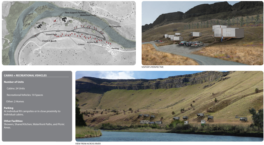
Working with the The Confederate Tribes of Warm Springs, PMA created a prototype model, easily constructed and assembled off site (test fit), then transported to the site and efficiently erected. The prototype was designed to be economical and constructed from lumber from the local lumber mill that produces products from high desert pines. A contemporary design style was chosen to harmonize with existing mid-century Belluschi homes on the property. Both the Belluschi homes and the Eco-Huts stand in contrast with the landscape and topography.

    Elevation-pmapdx-design

    Perspective-pmapdx-design
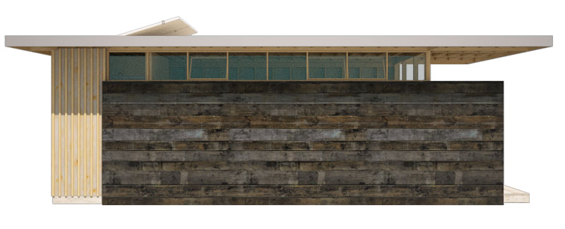
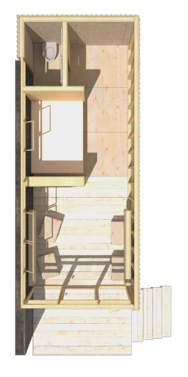
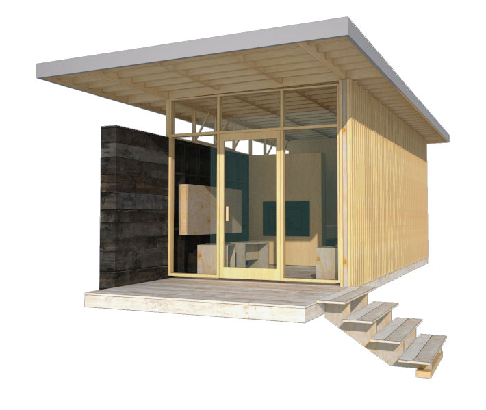
Conceived to have minimal footprints on the land, the Huts rest on piers elevating the floor above the land and accommodating the undulating landscape. A modular dimension was chosen permitting variation in the Eco-Hut sizes. The floor, walls, and roof planes are built off-site and tilted in place. Exterior stained wood material varying from plywood to sawn boards were chosen to harmonize with the High Desert landscape and be of minimal maintenance to the Tribes. Plywood panels are dressed with battens and either in-set from the wood framing or installed flush to the exterior. Sawn mill boards are stained dark desert grey and applied horizontally to create solid side walls atop of which are placed ribbon windows. The primary entry and view wall is a wood frame window and door façade. A deep roof overhang protects the interior from solar gain. Interiors are exposed panel faces or stained mill boards. Partial height walls denote areas of more privacy. The process of assembling the Eco-Huts on-site and disassembling them in the future determined the material pallet of dimensional lumber and pre-assembled wood window walls. The prototype incorporates modular concepts enabling variation in floor plan and amenities in direct response to the Owner’s request for market flexibility.

    Section-pmapdx-design
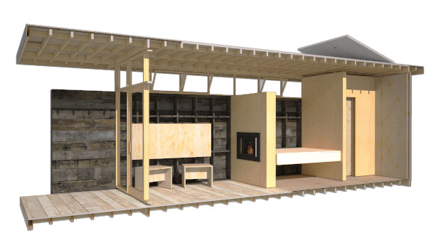
Inherent in our design approach for the Eco-Huts is the creation of design solutions that emphasize the uniqueness of Place. The concept includes Land Restoration and Land Stewardship. PMA’s goals when designing the prototypes was to help enhance the natural beauty of the river edge by integrating a built structure into the landscape that has minimal disturbance to the site and will leave no footprint when removed. Willows, sedges, and juniper will be planted to provide riparian cover along the Deschutes River in an effort to increase fish habitat and mitigate flooding. The plantings will also help mitigate visual impact from the river. The lumber mill site’s river edge offers an opportunity to create an employee park and river restoration replacing equipment storage and log staging. The Eco-Huts offer an opportunity to test the integration of stewardship planning and place design.
    Plan-pmapdx-design

    Written by Peter Meijer AIA,NCARB, Principal